Parts
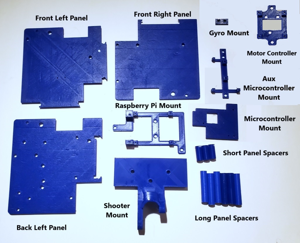
In addition to the four Swerve Modules you built in the previous chapter you will need the following 3D printed parts:
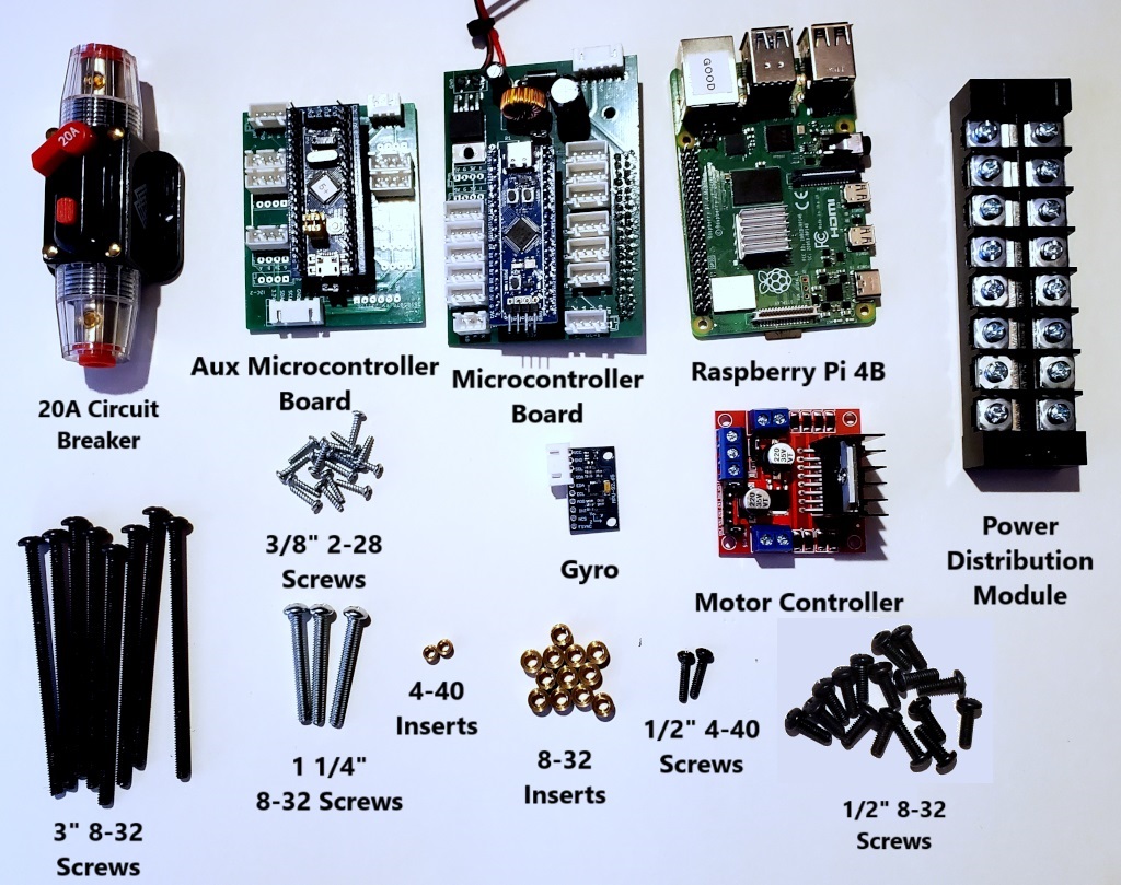
Plus the following hardware and electronics:
Assembling the Swerve Modules
First attach the Front Left Swerve Module to the Back Left Swerve Module using two 1/2″ 8-32 Screws as shown:
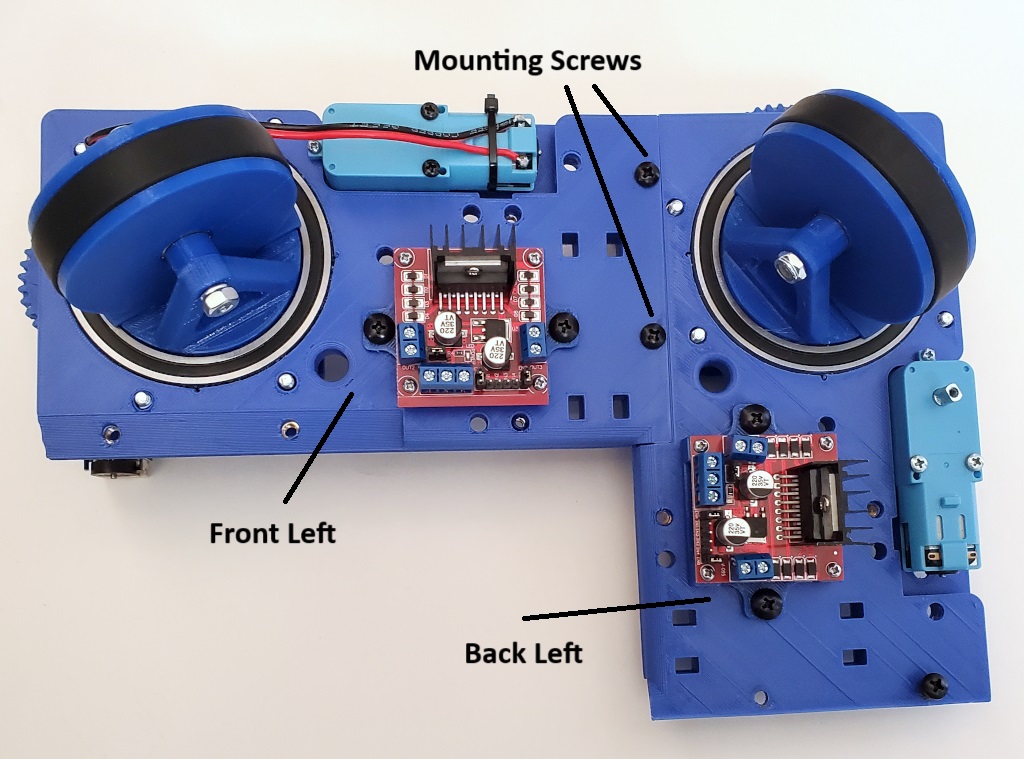
Then in a similar manner attach the Front Right and Back Right modules using six more 1/2″ 8-32 Screws as shown:
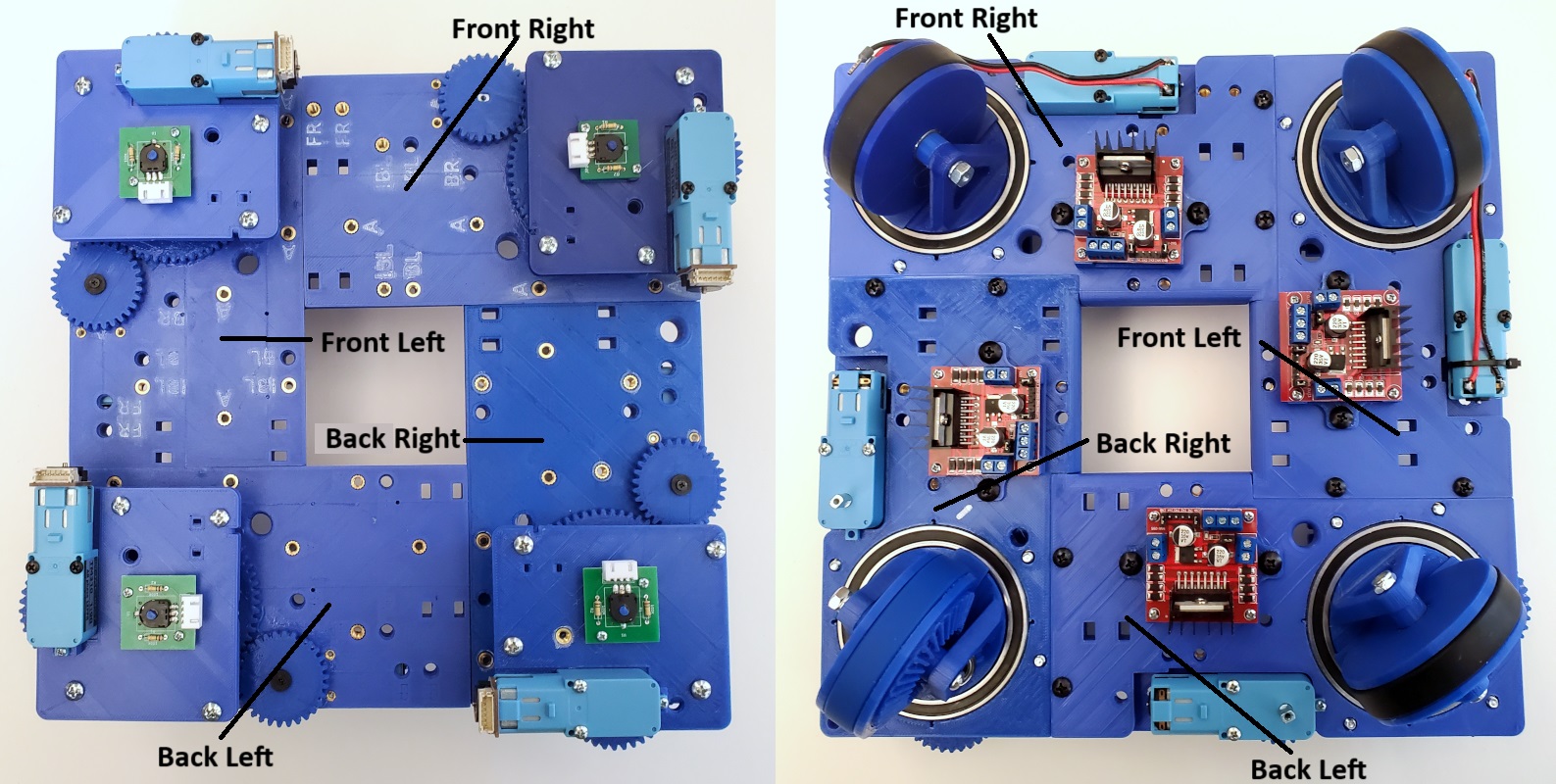
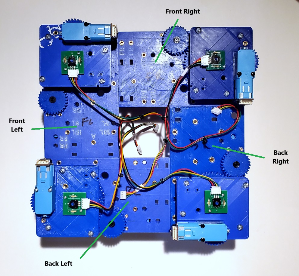
Finally connect the four Absolute Encoder cables into each of the four Encoders as show. Make sure that the labels on the cables match the Swerve Module.
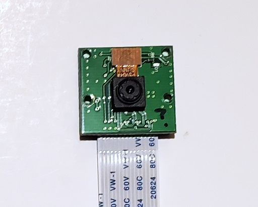
Pi Camera
Now attach a 30cm cable to the Pi Camera as shown:
Then mount the Pi Camera on the Pi Camera Mount using four 2-28 screws as shown. Be sure to use the backing plate as the heads of the metal screws can short circuit traces on the camera board:
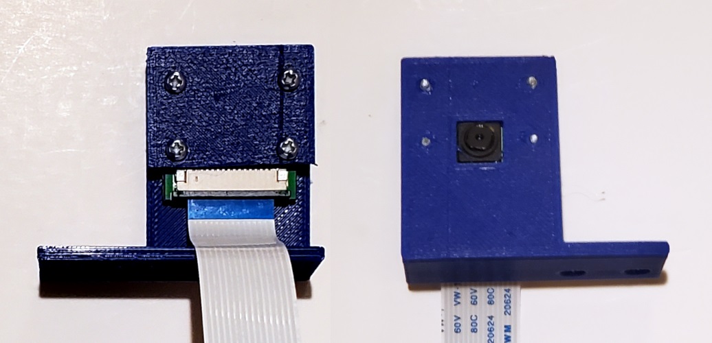
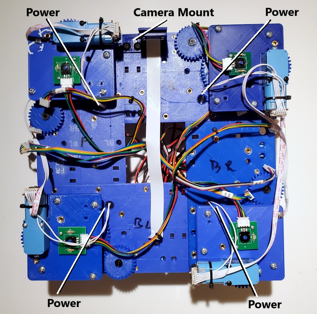
Finally Mount the camera on the Chassis using two 1/2″ 8-32 Screws as shown. Also take this time to run the Power Wires for the Drive Motors through the holes in the Swerve Modules as shown.
Add Screw Inserts To Panels
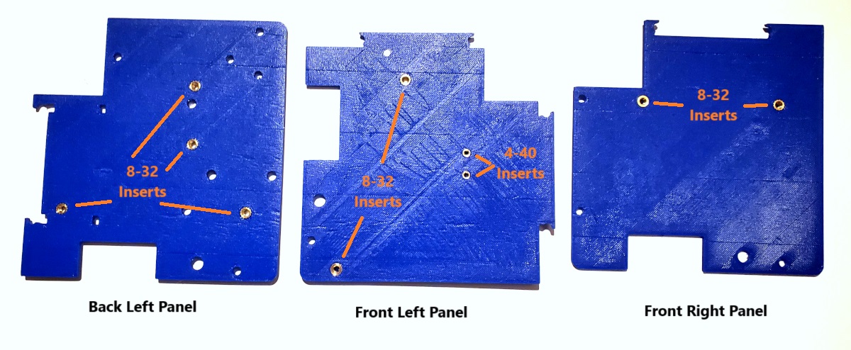
Next add screw inserts into the three Panels as shown below:
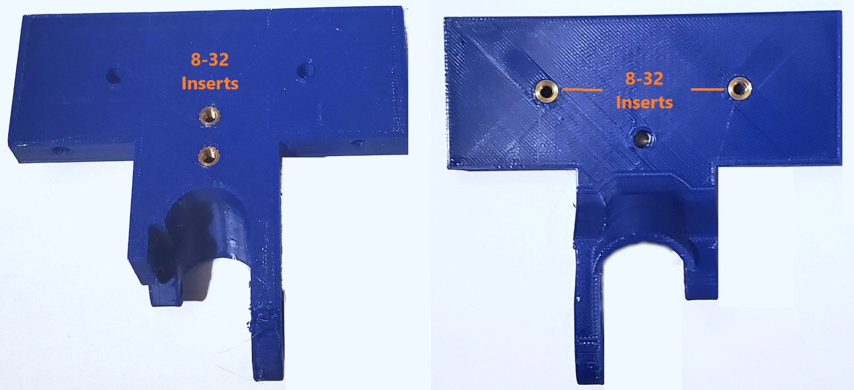
Then add four inserts to the Shooter Mount as shown below:
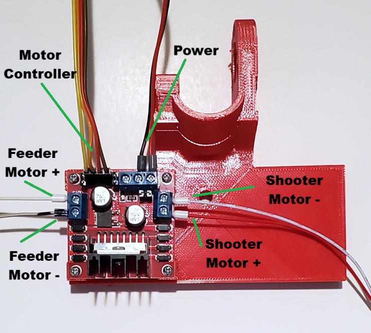
Now mount the Motor Controller Mount to the Shooter Mount using two 1/2″ 8-32 screws. Then attach the Motor Controller to the Motor Controller Mount using four 3/8″ 2-28 Screws and connect the power, motor controller, shooter motor and feeder motor wiring as shown below. We are connecting these now because once assembled the Motor Controller will no longer be as easily accessible.
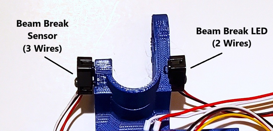
Then attach the Beam Break Sensor to the Shooter Mount using two 4-40 Screws. We did not use inserts here, you should be able to screw the screws directly into the plastic. Note that the sensor has three wires and goes on the left as shown:
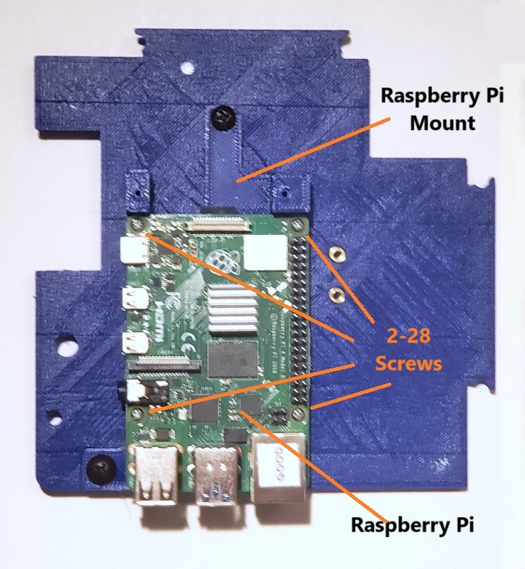
Next mount the Raspberry Pi Mount to the Front Left Panel with two 1/2″ 8-32 Screws and attach the Raspberry Pi to the mount using four 3/8″ 2-28 Screws.
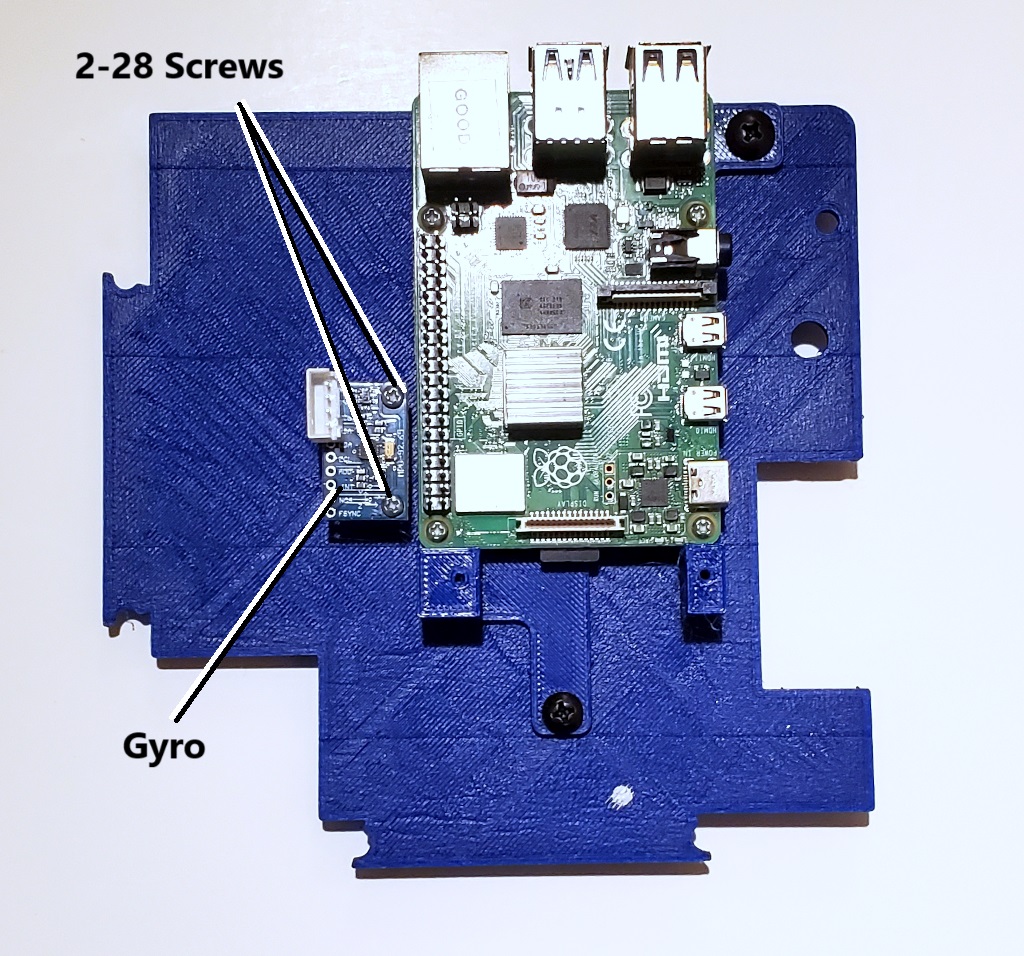
Now attach the Gyro Mount to the panel using two 1/2″ 4-40 Screws and attach the Gyro to the Gyro Mount using two 3/8″ 2-28 Screws as shown:
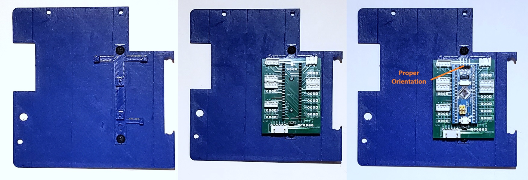
Then mount the Aux Microcontroller Mount to the Front Right Panel with two 1/2″ 8-32 Screws. Then mount the Aux Motor Controller to the mount using two 3/8″ 2-28 Screws and insert the Microcontroller making sure it in the proper orientation as shown:
It is now time to assemble the remainder of the Chassis. For this you will need eight 3″ 8-32 Screws, three 1 1/4″ 8-32 Screws, six Long Panel Spacers and three Short Panel Spacers. Assemble them all together as shown below:

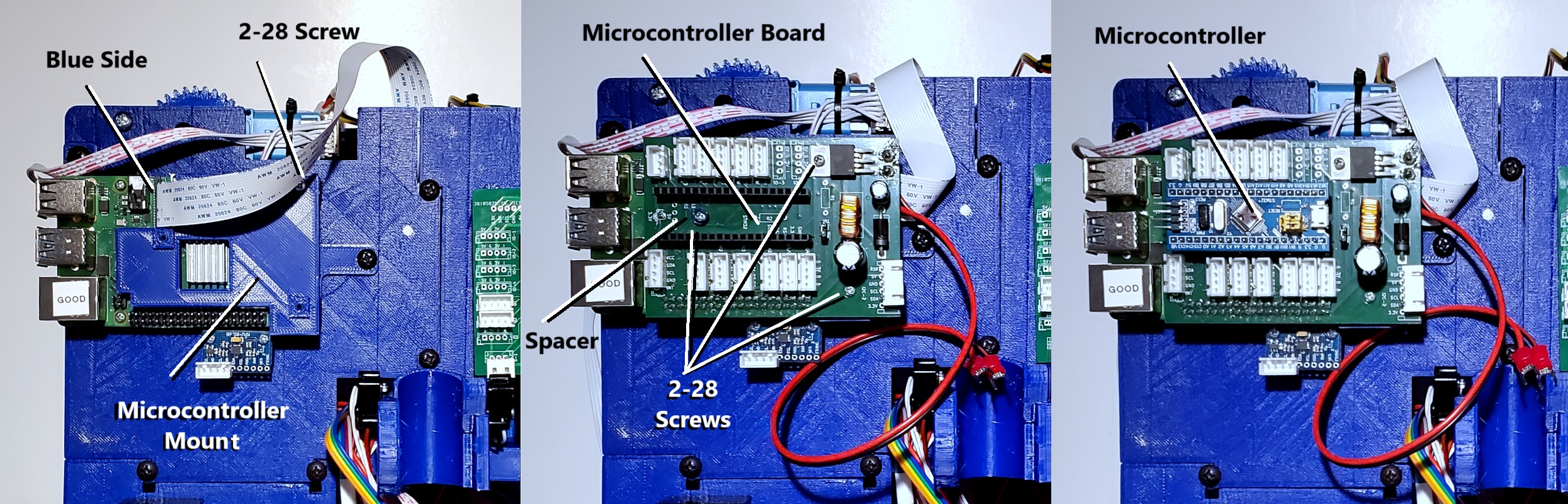
Then connect the Camera Cable to the Rasberry Pi making sure that the Blue Side faces the USB connectors as shown. Then attach the Microcontroller Mount to the Raspberry Pi Mount using a 3/8″ 2-28 Screw as shown. Then attach the Microcontroller Board using three 3/8″ 2-28 Screws and the one Spacer as shown. Finally insert the Microcontroller into the socket on the Microcontroller Board as shown: