These are the instructions for assembling the Shooter using the older version of the Feeder which may be less reliable.
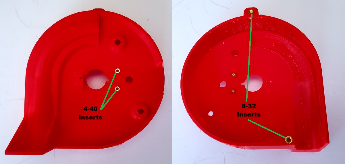
First install two 8-32 and two 4-40 inserts into the Feeder as shown.
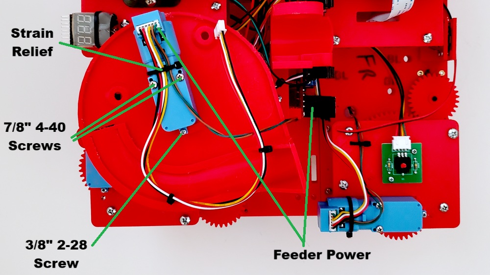
Now connect the Feeder Cable which you previously connected to the Feeder/Shooter Motor Controller to the Feeder Motor. Then attach the Feeder Motor to the bottom of the Feeder with two 7/8″ 4-40 screws and a 3/8″ 2-28 screw as shown. Make sure that you add the Strain Relief zip tie as shown:
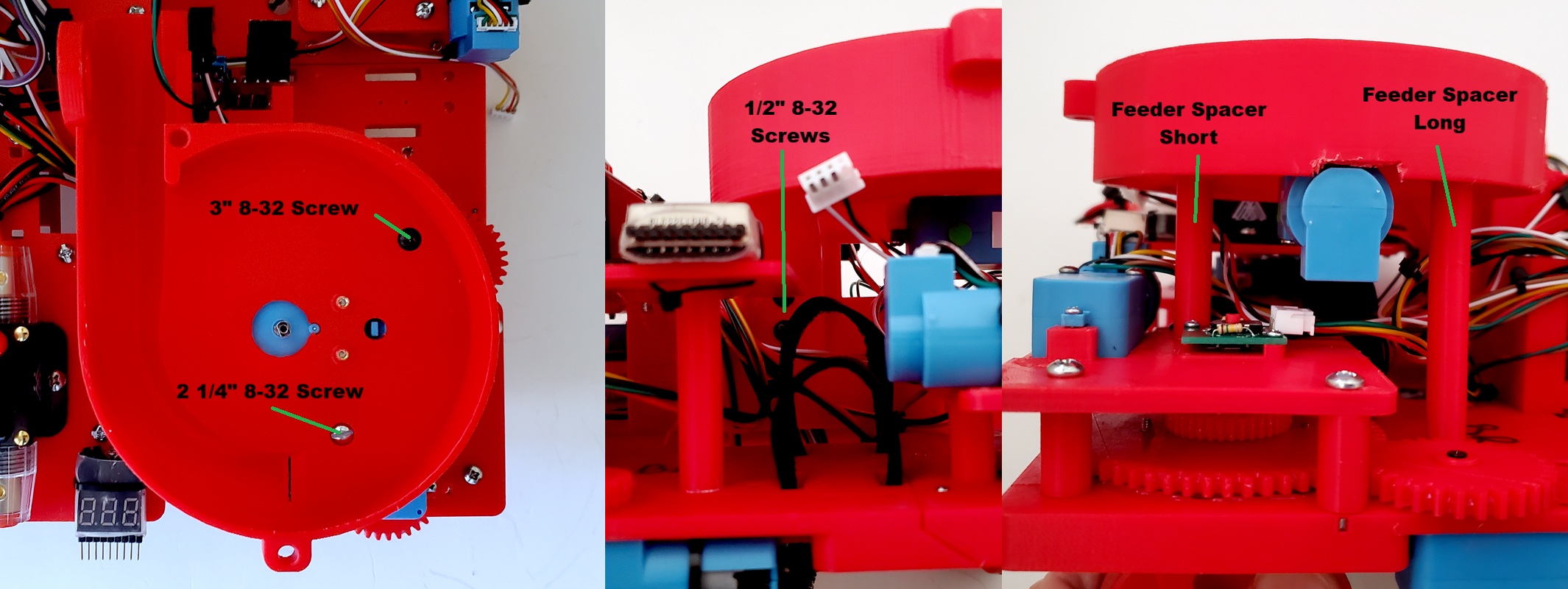
Next attach the Feeder to the Shooter Mount using the 8-32 screws and Feeder Spacers as shown:
Then attach the Rotor Insert to the Feeder Motor and tighten the 4-40 Set Screw as shown:
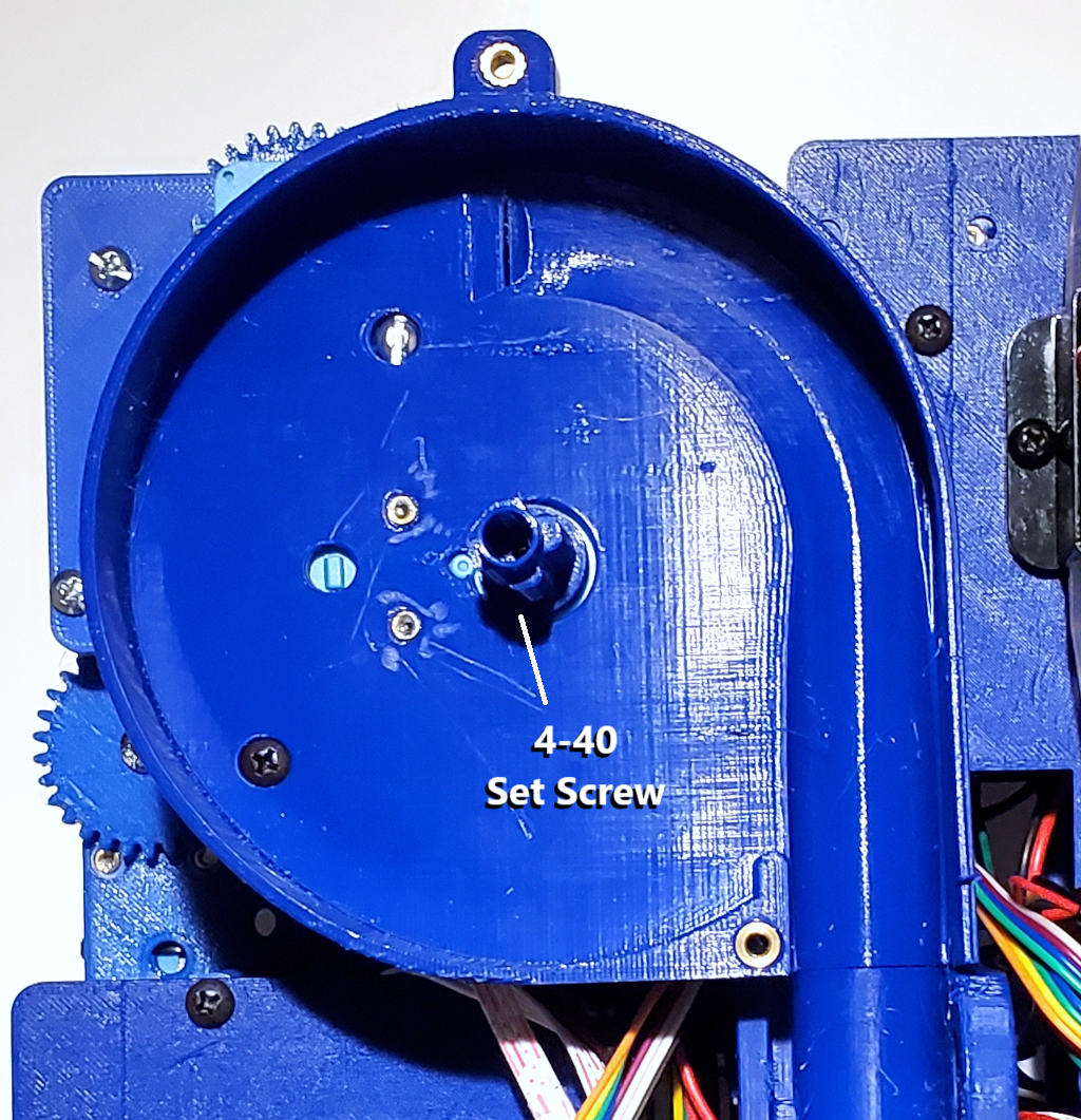
Next slide the Rotor over the Rotor Insert as shown:
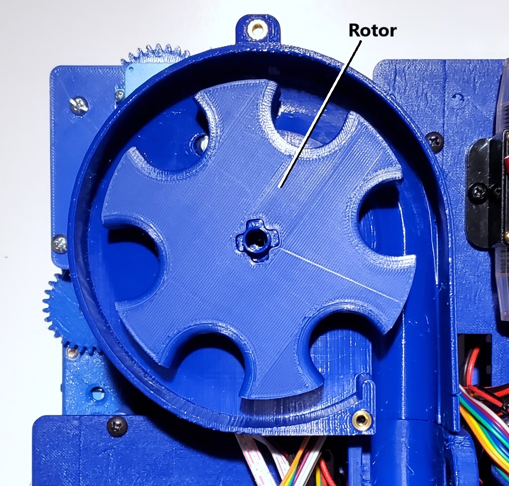
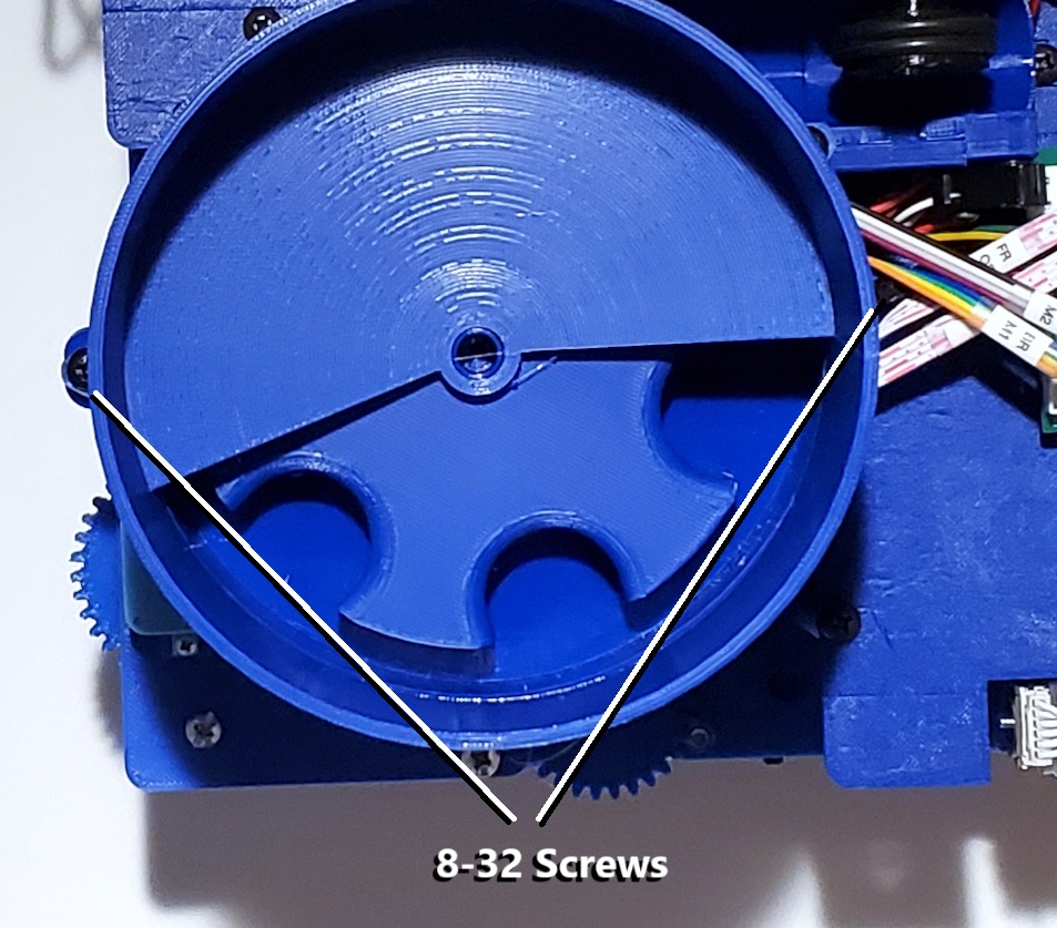
Then attach the Hopper using two 1/2″ 8-32 Screws as shown:
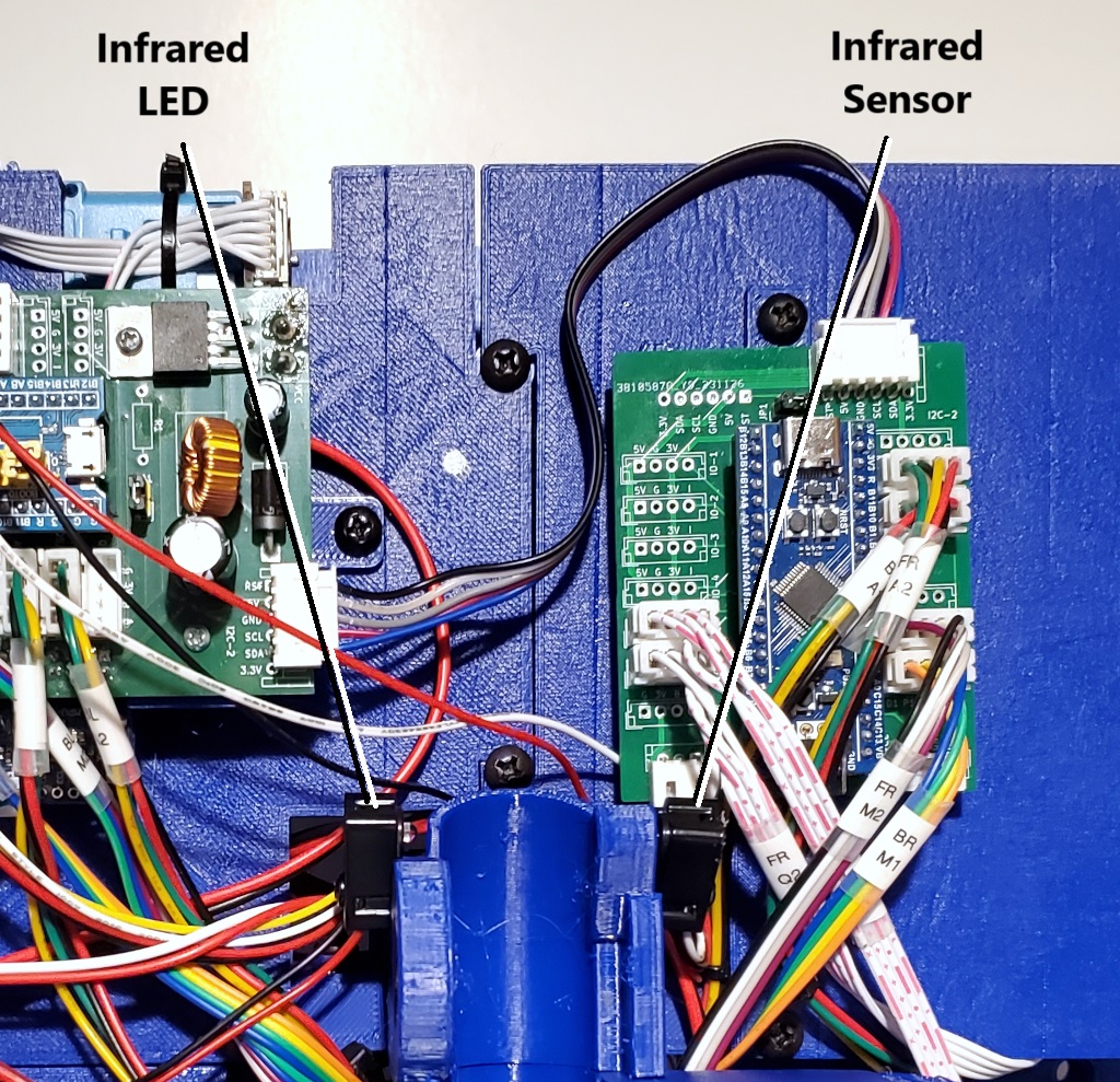
Now crimp the JST connectors to the Beam Break Sensors as shown: Note that the LED has two wires and the Sensor has three. Also note the order of the connections.

Next mount the Beam Break Sensors using two 4-40 Screws as shown. Note that the Infrared Sensor (the one with 3 wires) is the one on the right. We did not install inserts on the holes in the Shooter Mount. You should be able to screw the 4-40 Screws directly into the mount.
Now mount the Shooter Motor to the Shooter Mount using three 4mm 2.5 M Screws as shown. Warning: using screws that are longer than 4mm can cause damage to the motor (don’t ask me how I know this).
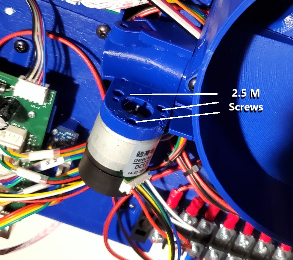
Then press fit the Flywheel onto the Shooter Motor shaft as shown:
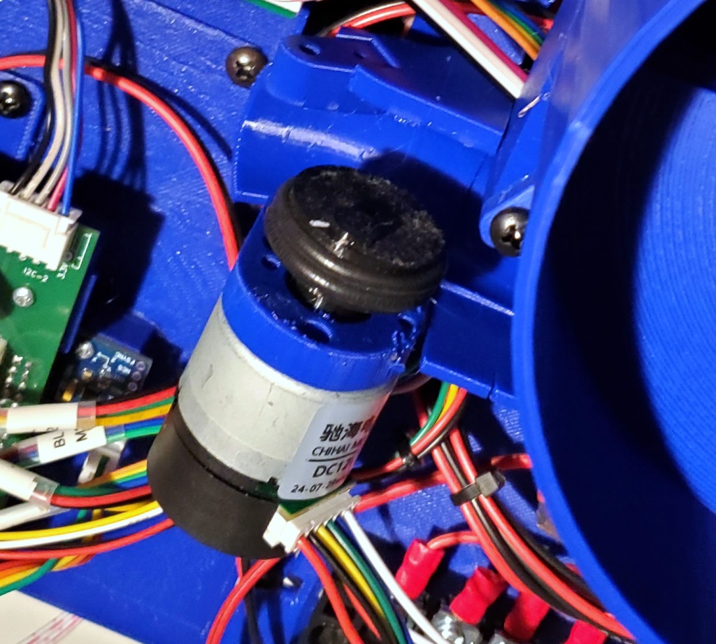
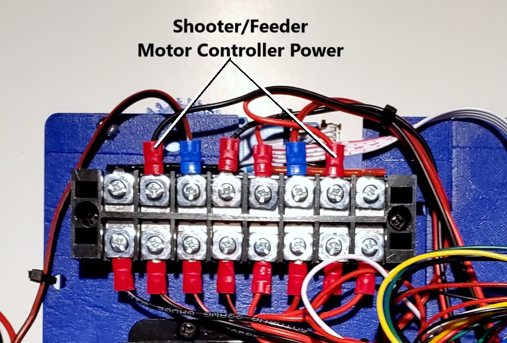
Finally, connect the Shooter/Feeder Motor Controller power as shown: