Parts
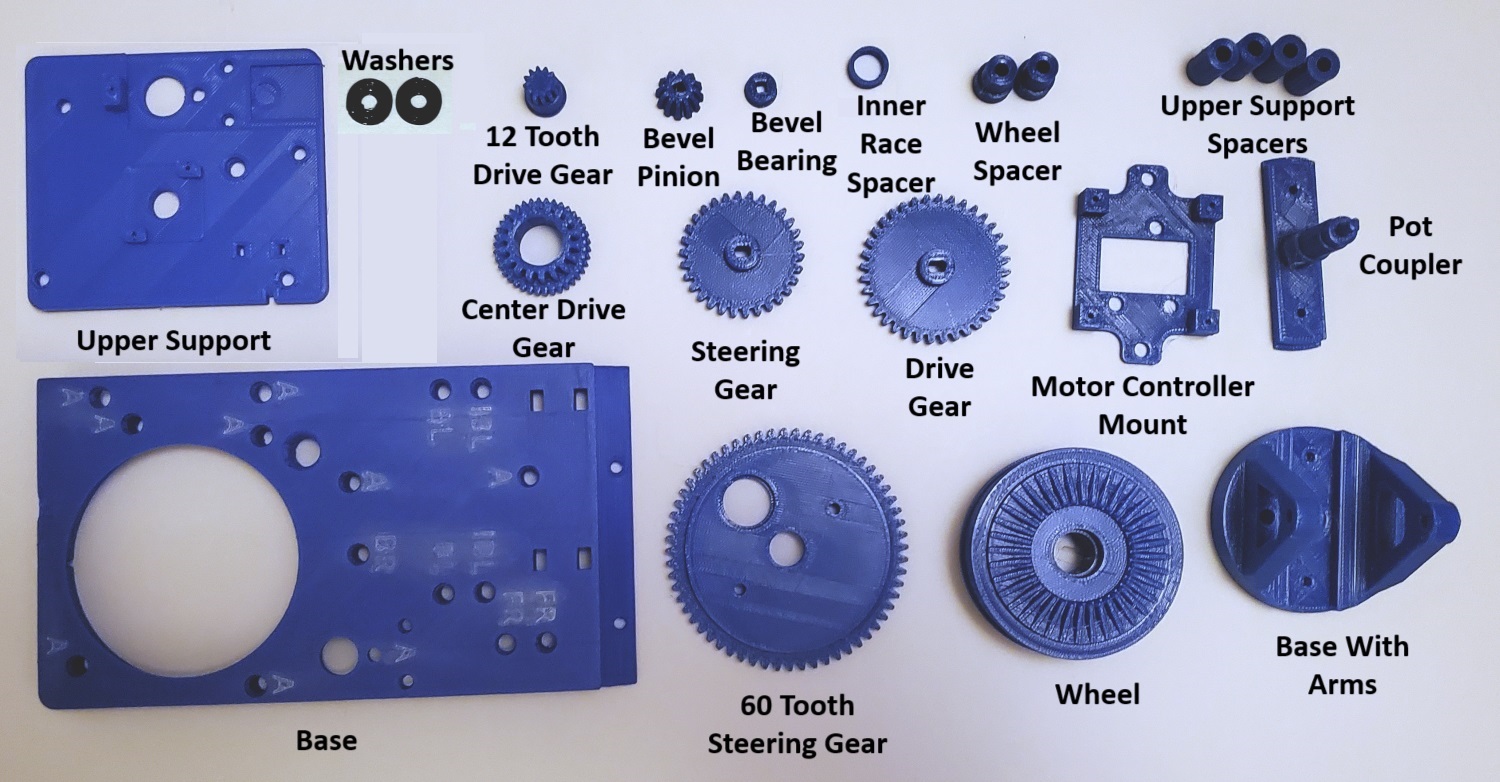
The robot consists of four swerve modules. To assemble each module you will need the following 3D printed parts:
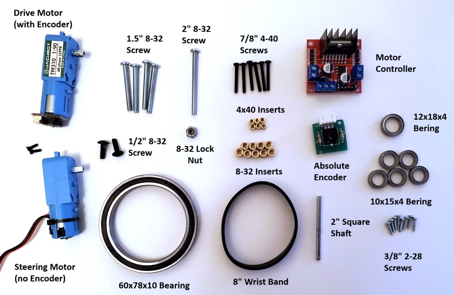
And the following set of hardware:
Applying the inserts
Note, if you printed the versions with the imbedded nuts, you will not need to use inserts and can skip this part.
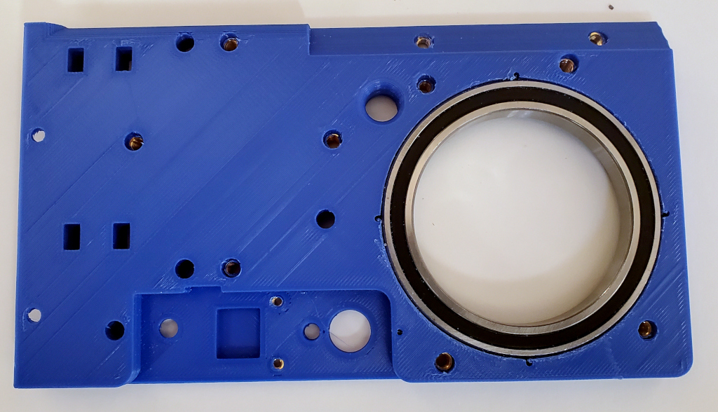
The first thing you are going to need to do is insert the various inserts into the Base, 60 Tooth Steering Gear, and Upper Support. In the case of the Base, the positions of the inserts depends on the corner of the robot. If you look at the Base, you will see it is marked with letters:
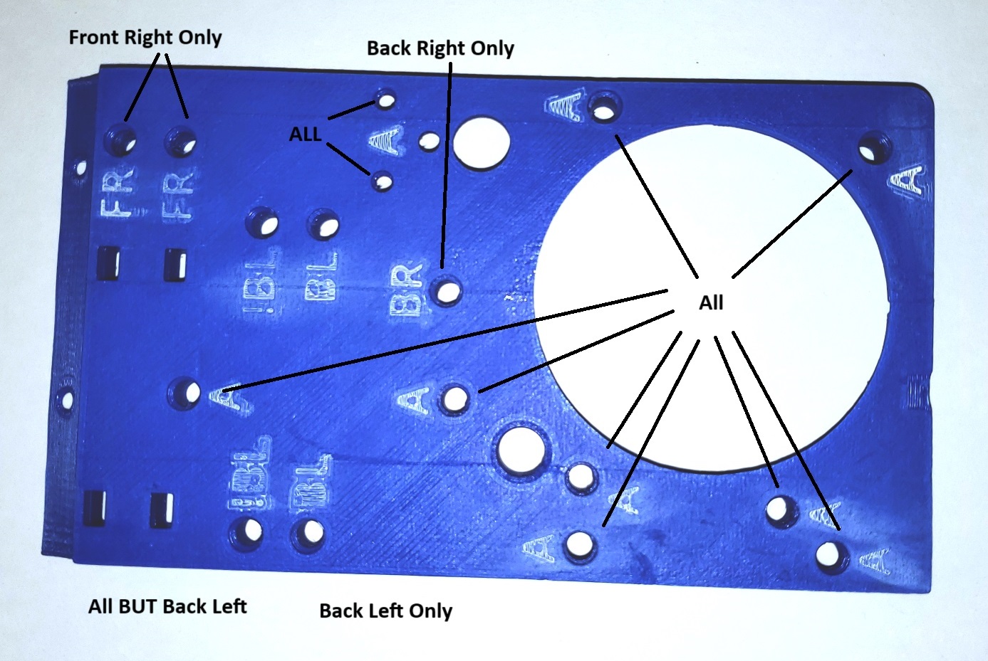
The holes marked with an A should have inserts for all four corners. The holes marked with BL should only have inserts for the back left corner. The holes marked !BL should have inserts for all corners except the back left. The holes marked FR should only have inserts for the front right corner. Finally the hole that is marked BR should only have an insert for the back right corner.
Also, the Upper Support part has a only one hole for a 8-32 insert and that insert should only be applied for the Back Left Corner.
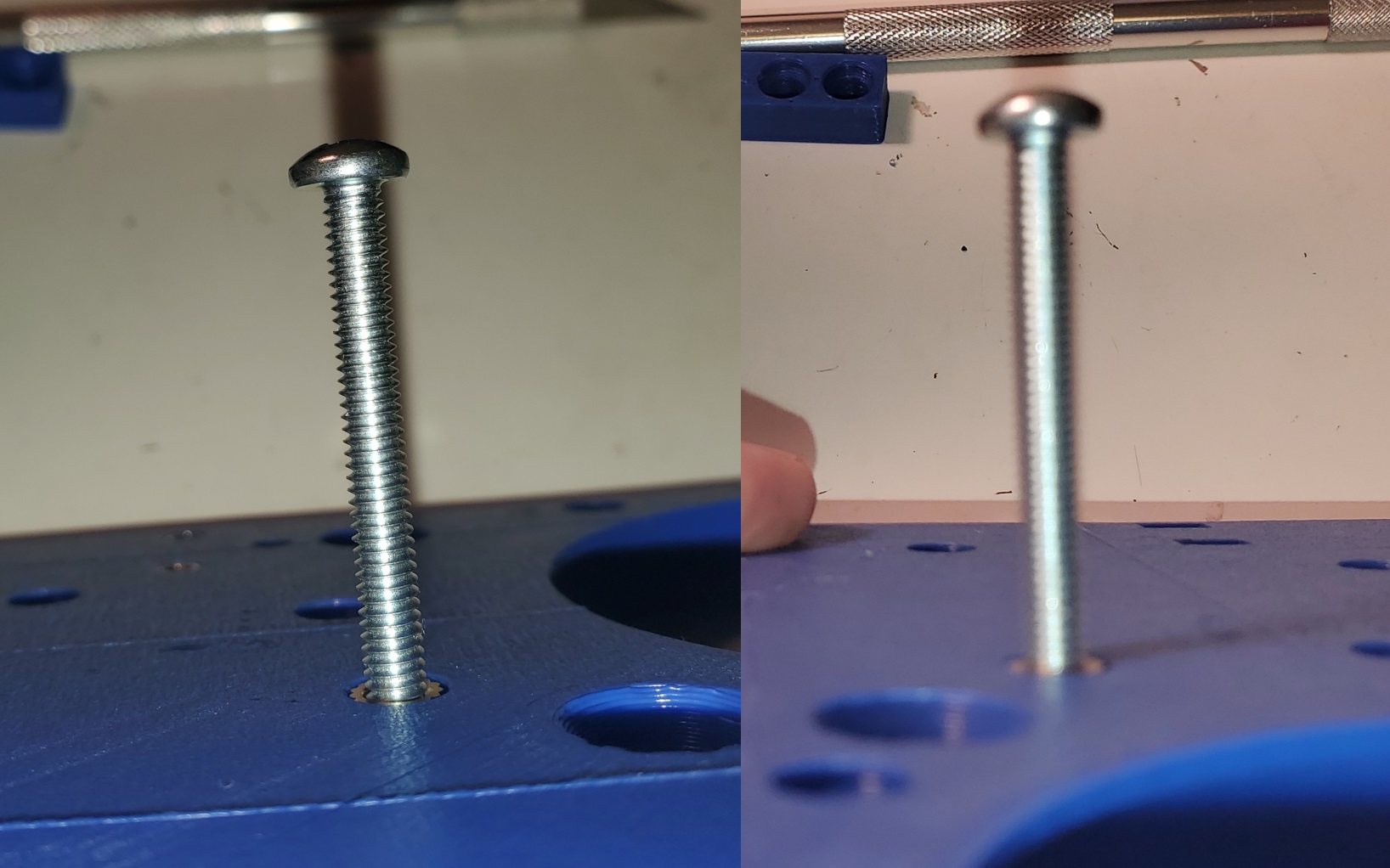
There are two ways you can apply the inserts. The first is to use a normal soldering iron as shown below:
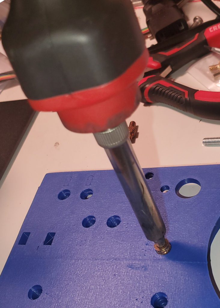
Apply the iron (temperature ~250° F) as shown. As the insert heats up you will be able to push it into the hole. Note that you do not need a lot of pressure. You should try and keep the soldering iron as vertical as possible. After the insert is all the way in, you should immediately check to see if it is in straight by screwing in a bolt and viewing it from various angles:
If you do this right after you apply the insert, the plastic will be soft enough that you can reposition it if necessary. Note that if you later find that one of your screws is not straight, you can fix it by using a soldering iron to reheat the insert until the plastic is soft enough to reposition it.
The second way to apply the inserts is to use a tool such as this one. While this tool helps get the inserts straight, it is by no means foolproof and you should still check to make sure that they are straight.
If you really don’t want to be bothered by the inserts, you can, if you wish, use longer bolts and have them go through the holes and attach with a nut on the other side. However, despite the fact that applying them is a bit of a pain, you will find that it well worthwhile as it make assembling the robot much easier.
Once you have applied the inserts and let them all cool, you need to check the other side for plastic that has been pushed into a position that partially blocks the screw:
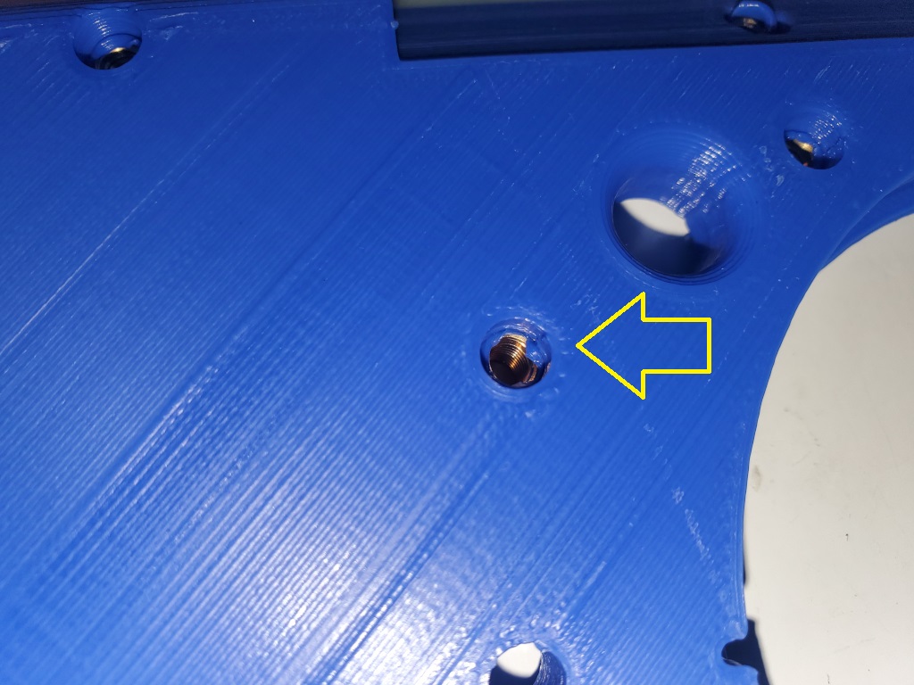
You should use a exacto knife to clean out the blocking plastic and then run a bolt all the way through to make sure it is clear.
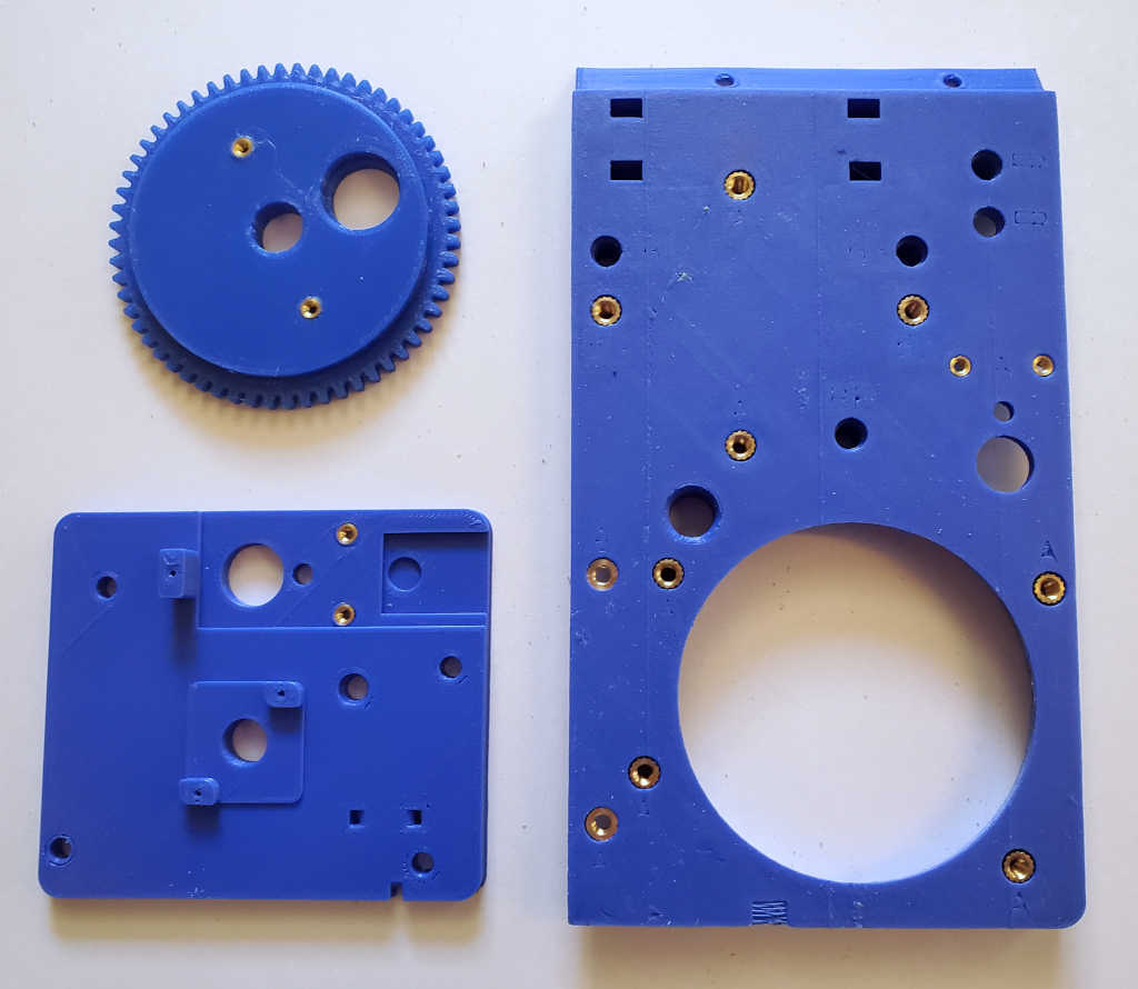
The following shows the 3 parts that require inserts after the inserts have been applied. Note that these insert positions are for the Back Left Corner.
Assemble the wheel
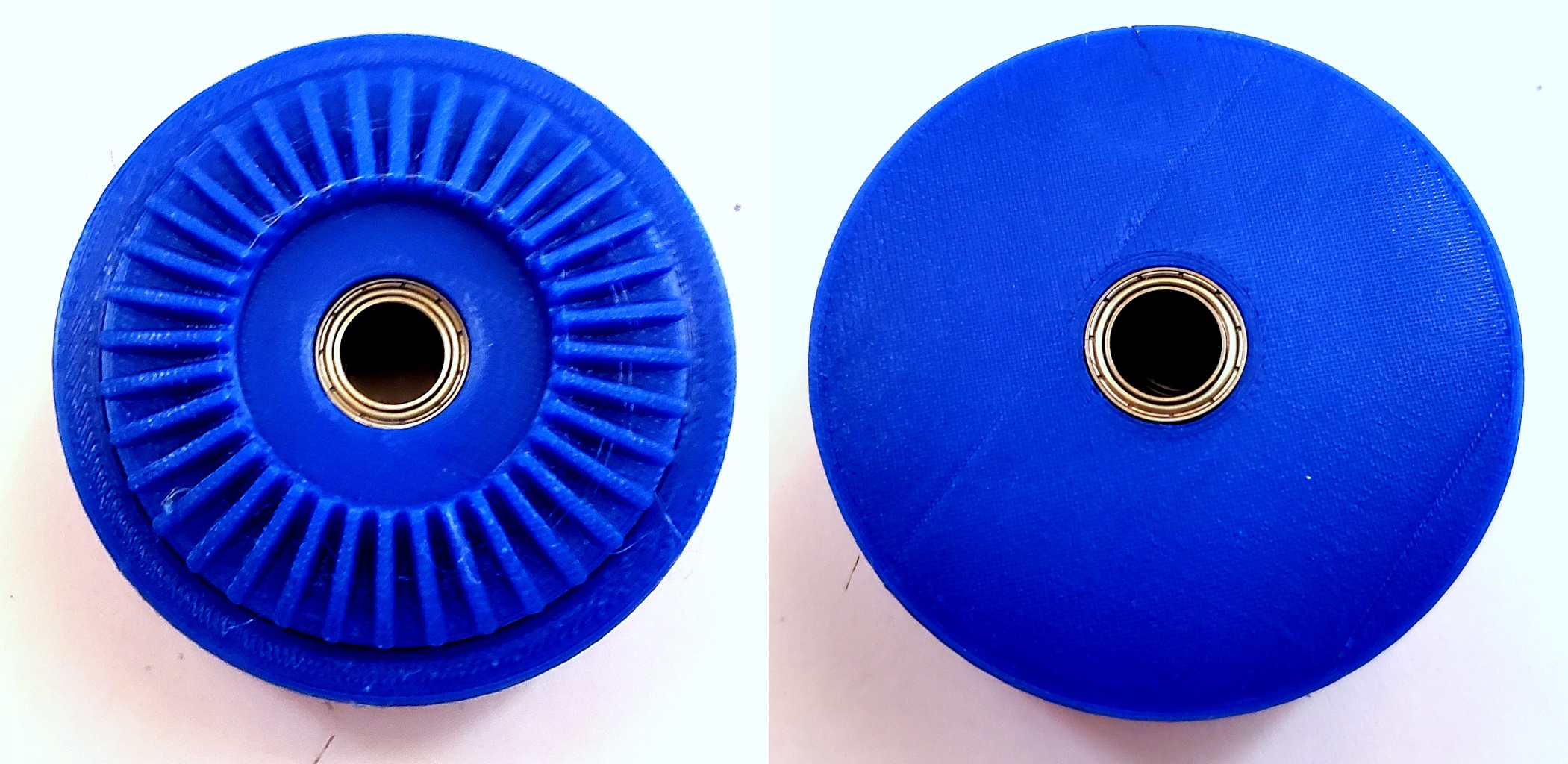
Insert a 10x15x4 Bearing into each side of the wheel as shown:
Now insert the two Wheel Spacers into the wheel bearings as shown:
Then place the rubber Wrist Band around the wheel for traction as shown:
Assemble the Base
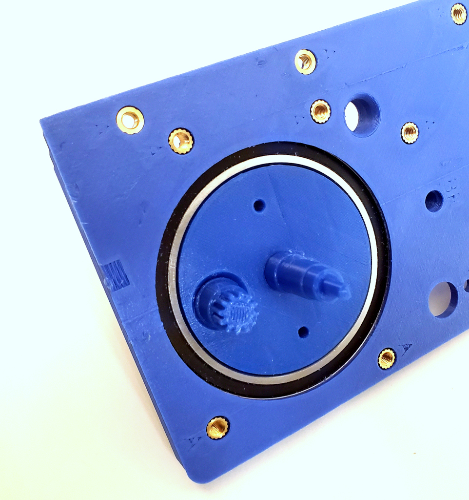
First insert the 60x78x10 Bearing into the Base as shown:
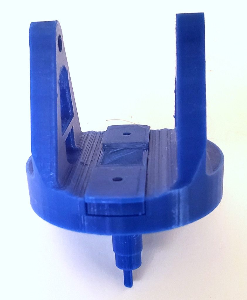
Next insert the Pot Coupler into the Base With Arms as shown:
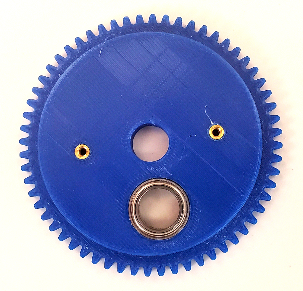
Then insert the 12x18x4 Bearing into the 60 Tooth Steering Gear as shown:
Next insert one of the 10x15x4 Bearings into the Base With Arms as shown:
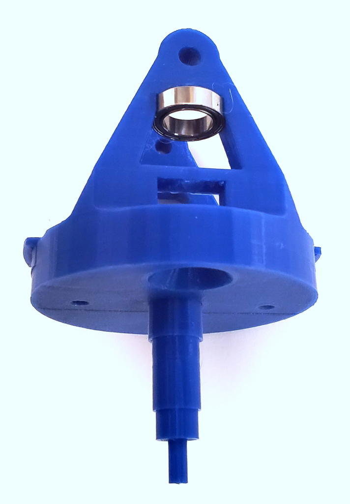
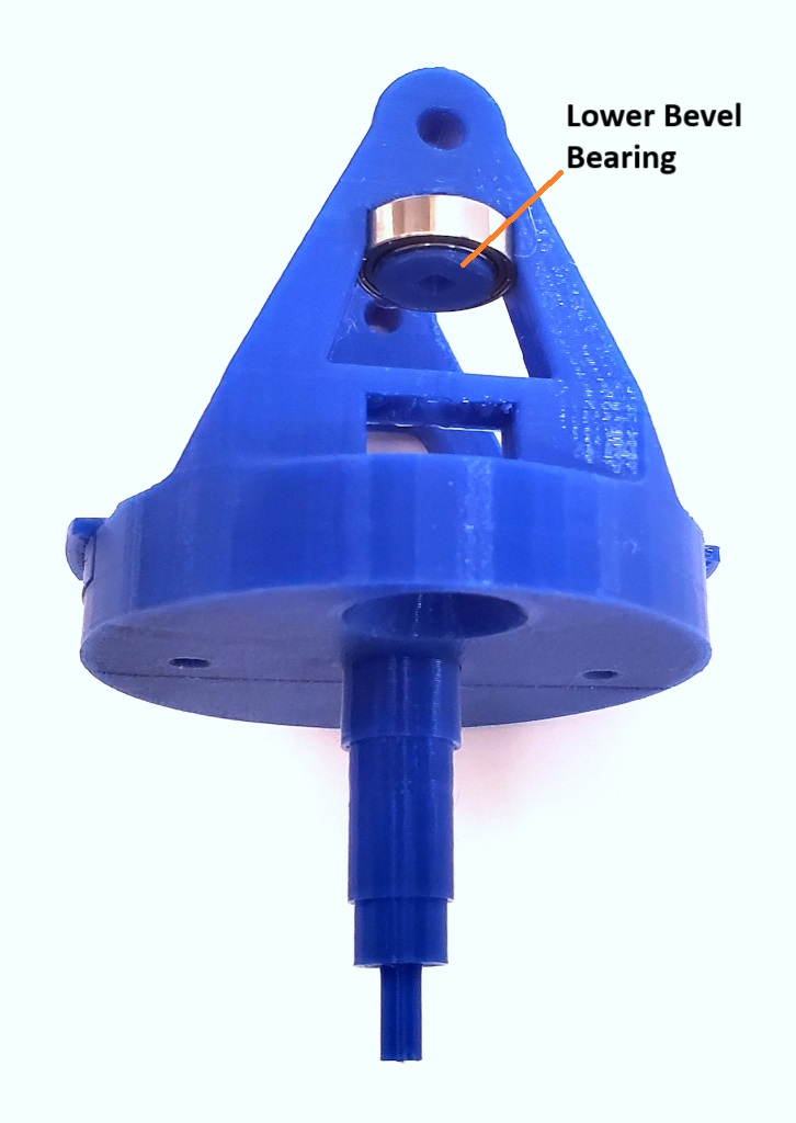
Then insert the Lower Bevel Bearing into the 10x15x4 Bearing that you just inserted into the Base With Arms as shown:
Now insert the Square Shaft through the Bevel Pinion and into the Lower Bevel Bearing as shown:
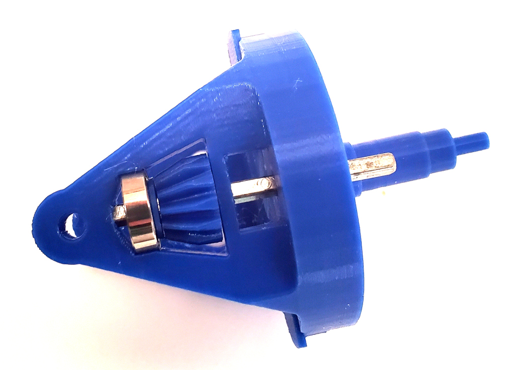
Next attach the 12 Tooth Drive Gear to the Square Shaft as shown:
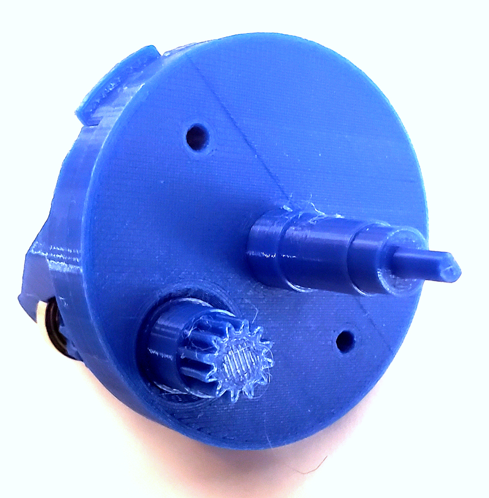
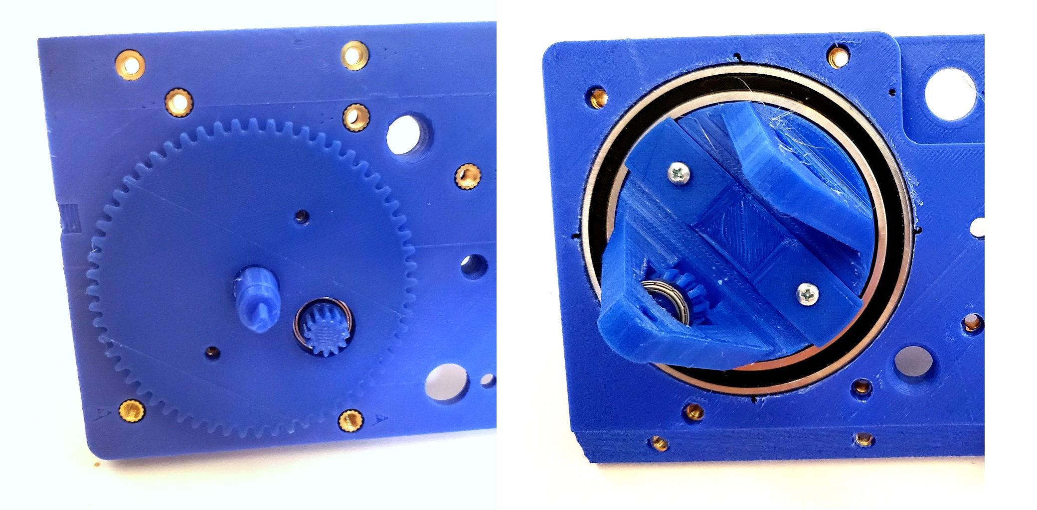
Then insert the Base With Arms into the Base as shown:
Now attach the 60 Tooth Steering Gear to the Base With Arms with two 7/8″ 4-40 Screws as shown:
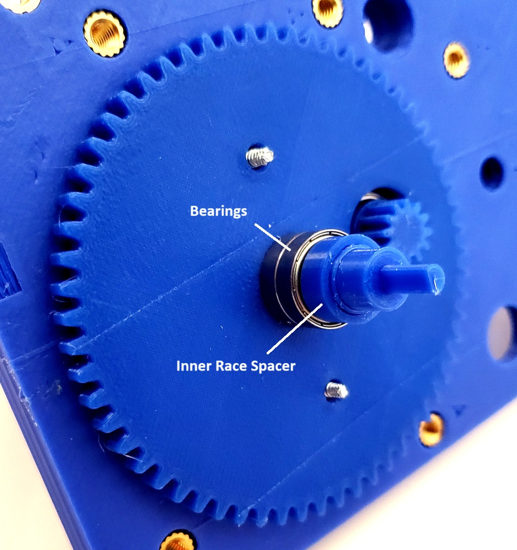
Then place two 10x15x4 Bearings on the Pot Coupler and lock them in place with the Inner Race Spacer as shown:
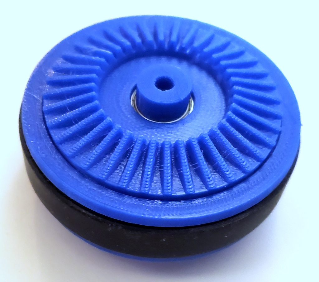
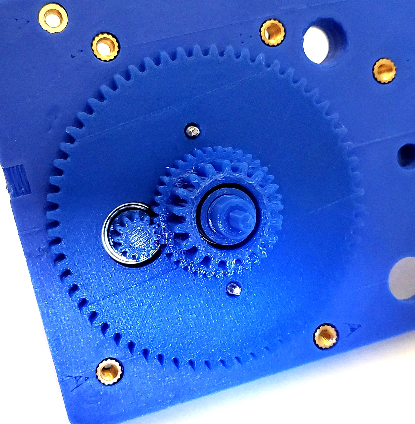
Now slide the Center Drive Gear over the two bearings that you just installed as shown:
Next, attach the Wheel to the Base With Arms with the 2″ 8-32 Screw as shown:
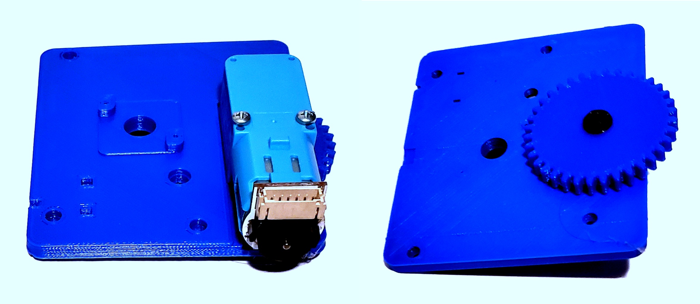
Now mount the Steering Motor (the motor that does not have an encoder) to the Base as shown:
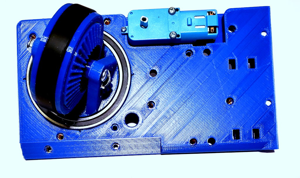
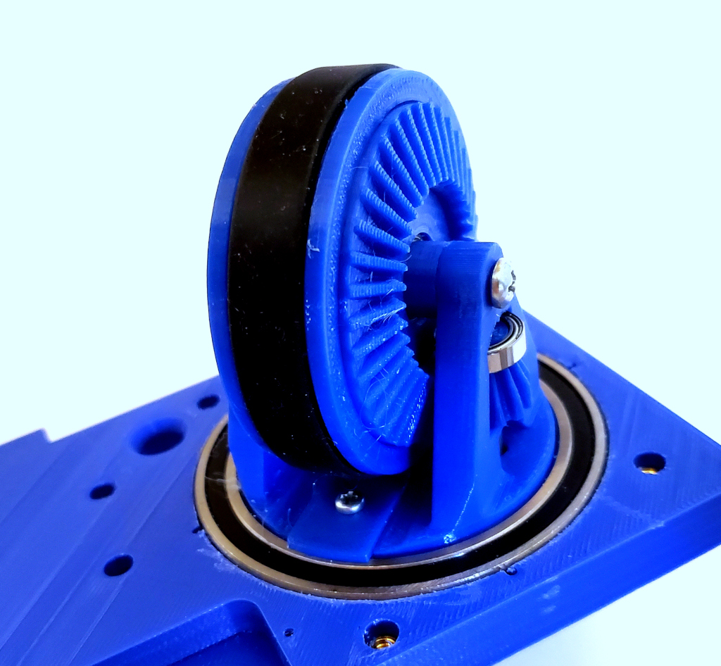
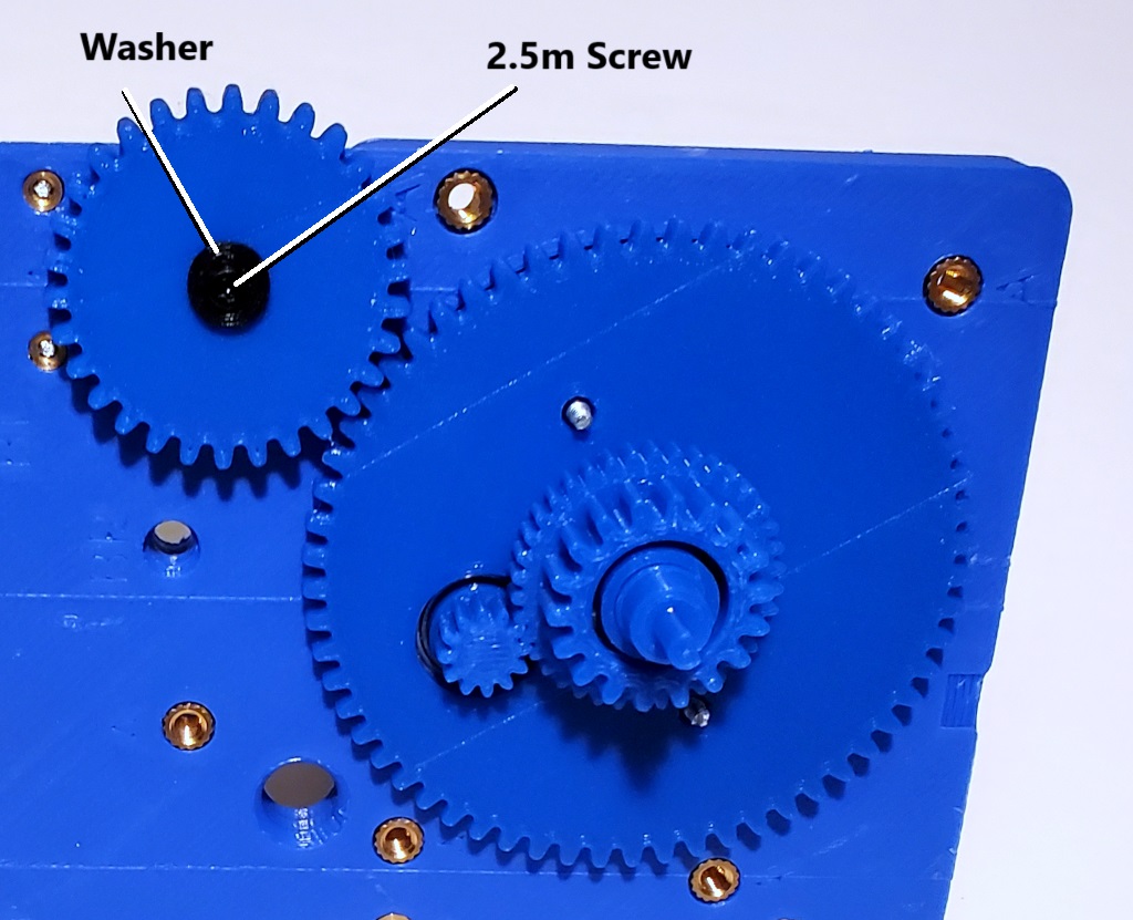
Finally, attach the Steering Gear to the Steering Motor using the washer and 2.5m Screws as shown:
Before you move on, you should apply a generous amount of your favorite gear lubricant to the gears. I have been using generic petroleum jelly for my lubricant and it seems to work well. Your milage might vary.
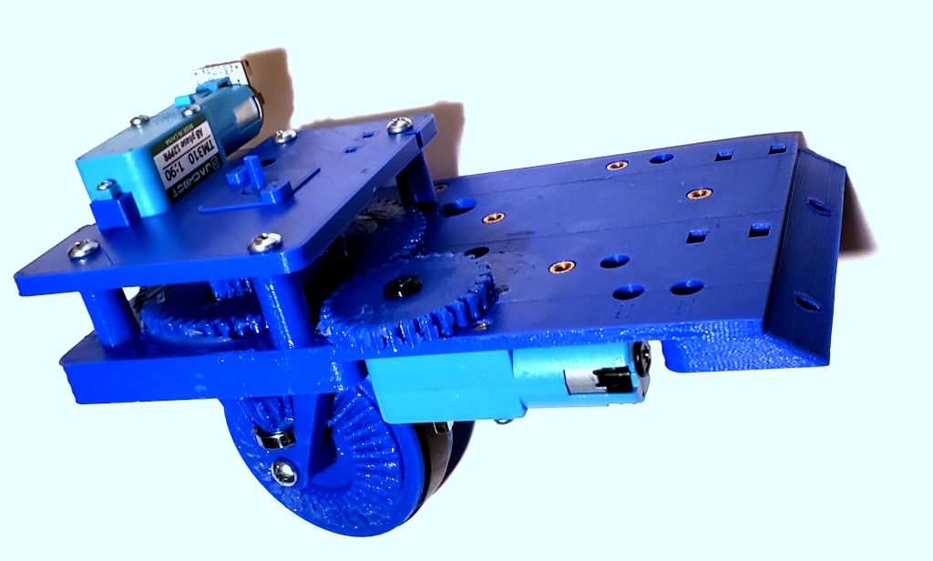
Assemble Upper Support
First attach the Drive Motor (the motor with the encoder) to the Upper Support and attack the Drive Gear with the Washer and a 2.5m Screw as shown. Once again apply a liberal amount of gear lubricant to the gear.
Next attach the Upper Support to the Base using the four Upper Support Spacers and four 1.5″ 8-32 Screws as shown:
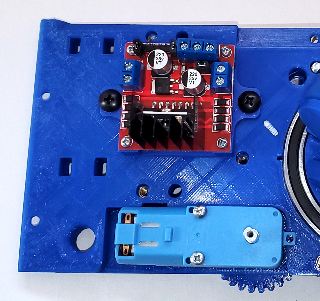
Then attach the Motor Controller Mount to the Base using two 1/2″ 8-32 Screws and attach the Motor Controller to the Mount using four 2-28 Screws as shown:
Now attach the Absolute Encoder to the Upper Support using two 3/8″ 2-28 Screws as shown:
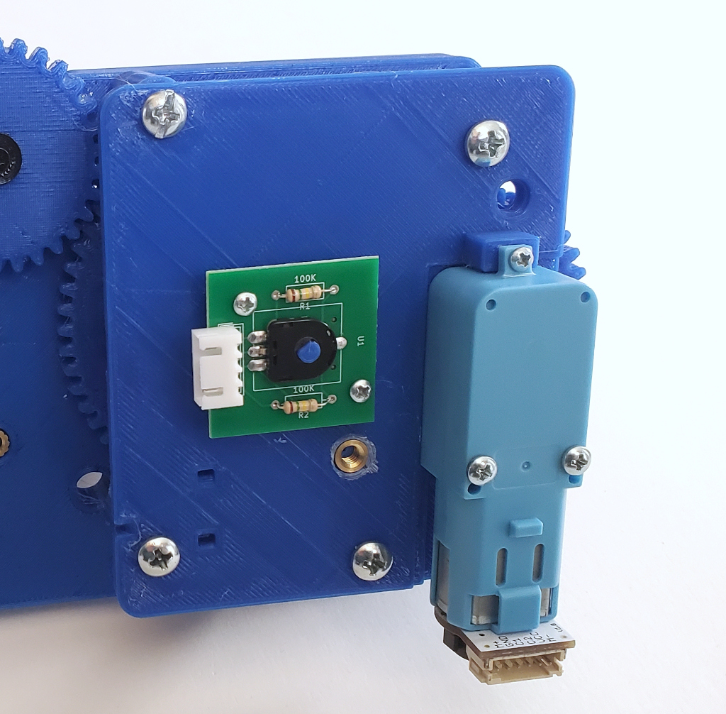
The Swerve Module is now complete. You will need to assemble four of these.