Before we continue, we need to create the wiring cables that we will need. We do this now so we can attach the cables as we assemble the robot so we don’t have to disassemble parts later to get to the components.
Creating theses cables requires crimping a number of connections. If you are unfamiliar with how to do this you can find some crimping tips here.
Absolute Analog Encoders
We will need four cables to connect the Absolute Analog Encoder for measuring the Swerve Module angle. Each of the cables should be wired as shown:
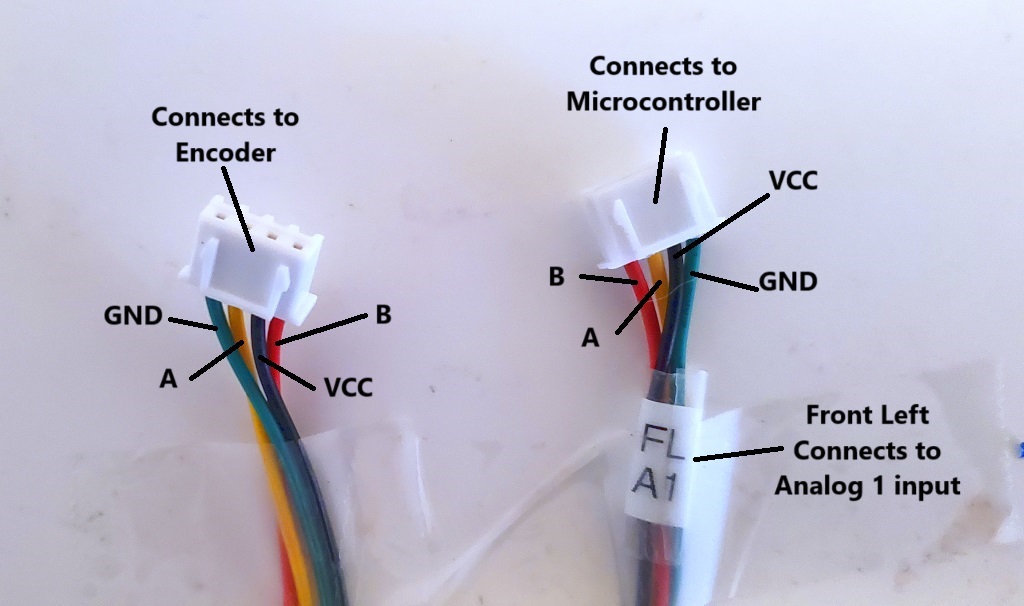
Pay close attention to the order of the wires for each connector. Also be sure to label the end of the cable that connects to the Microcontroller as follows:
- Front Left connects to the #1 Analog input of the Main Microcontroller (FL A1)
- Back Left connects to the #2 Analog input of the Main Microcontroller (BL A2)
- Back Right connects to the #1 Analog input of the Aux Microcontroller (BR A1)
- Front Right connects to the #2 Analog input of the Aux Microcontroller (FR A2)
Quadrature Encoders
We will need four cables for the Quadrature Encoders on the Drive Motors and one for the Feeder Motor. Each of the cables should be wired as shown:
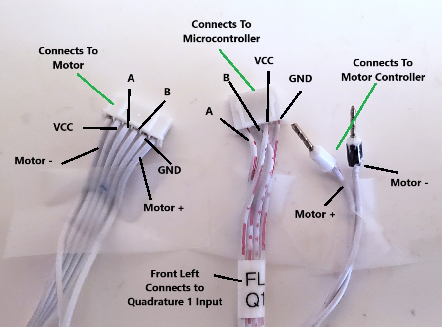
Pay close attention to the order of the wires. Label each of the five cables as follows:
- Front Left connects to the #1 Quadrature input of the Main Microcontroller (FL Q1)
- Back Left connects to the #2 Quadrature input of the Main Microcontroller (BL Q2)
- Feeder connects to the #3 Quadrature input of the Main Microcontroller (FDR Q3)
- Back Right connects to the #1 Quadrature input of the Aux Microcontroller (BR Q1)
- Front Right connects to the #2 Quadrature input of the Aux Microcontroller (FR Q2)
There is an additional Quadrature Encoder cable for the Shooter Motor which is slightly different and should be wired as shown:
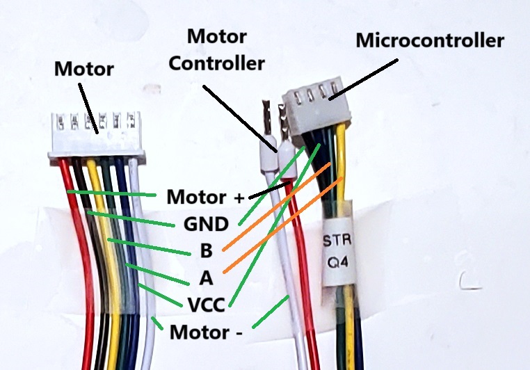
Once again pay close attention to the order of the wires. This cable should be labeled as the Shooter and connects to the #4 Quadrature input on the Main Microcontroller.
Motor Controller
You will need four Motor Controller Cables to connect the Motor Controller to the Microcontroller should be 30 cm long and wired as shown below:
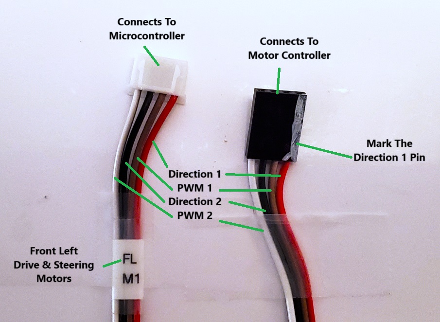
Note that in this case the cables just make a 1 to 1 connection. Don’t forget to label the cable. Also since the Motor Controller connector is not keyed you should mark the Direction 1 edge so you can orient it properly when plugging it into the Microcontroller board.
In addition to the control cable for the Motor Controller we will need a power cable. We will need five of these cables, one 11″ long and four 13″ long. On one end you should crip the power connectors to either end as shown below:
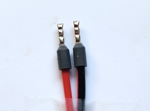
We will not be connecting anything to the other end of these cables at this time.
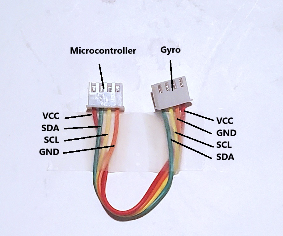
Gyro
Prepare a 10 cm cable for the connection for the Main Microcontroller to the Gyro as follows:
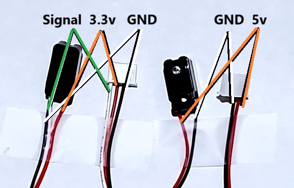
Beam Break Sensor
Wire the Beam Break Sensor as shown: