If you chose to print the Complete Chassis, then you are good to go. If you printed the chassis parts separately, then you need to assemble them according to the following image:
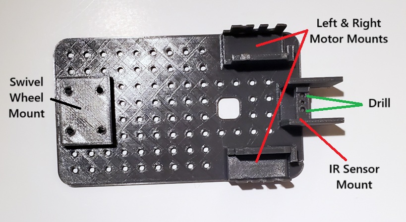
Note that in either case you need to drill out the two holes as indicated. These holes were designed with one solid layer so they can be printed without the need for support.
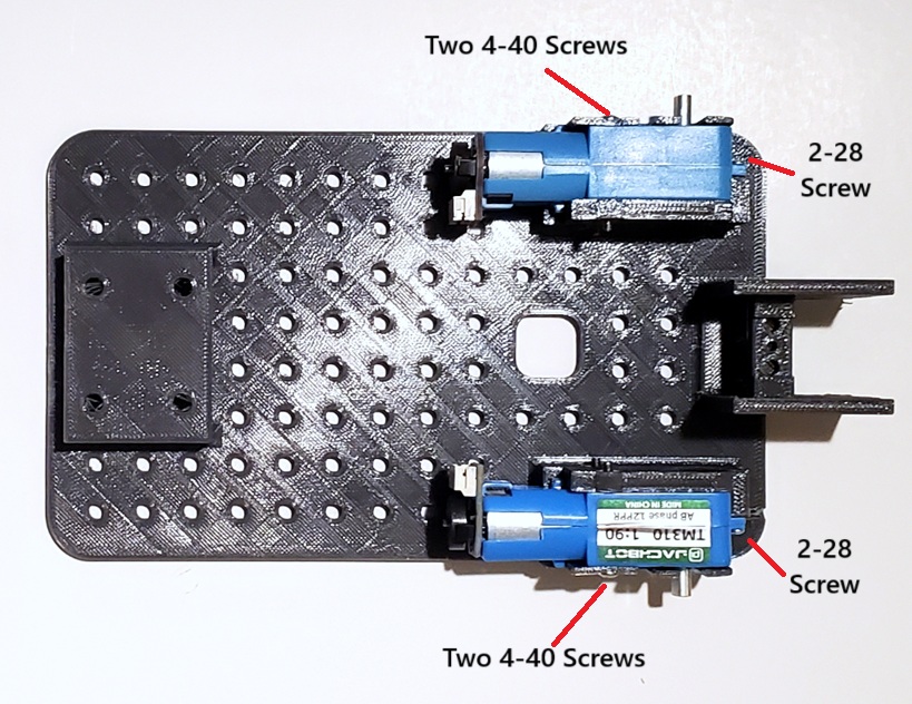
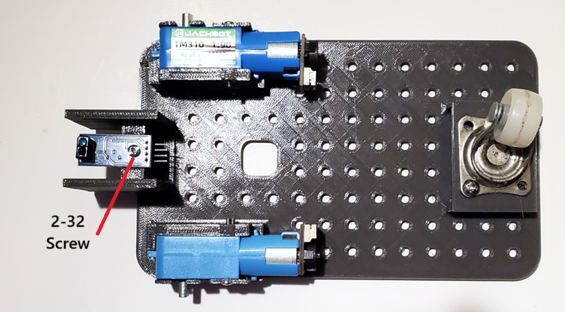
Now attach the two drive motors as shown below:
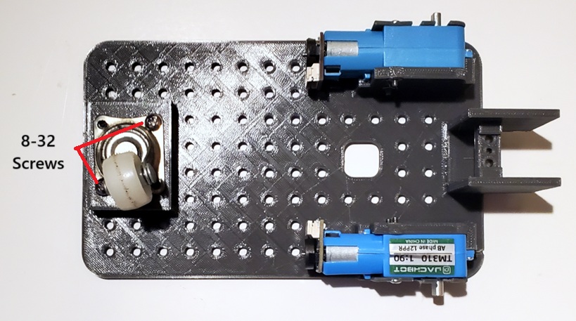
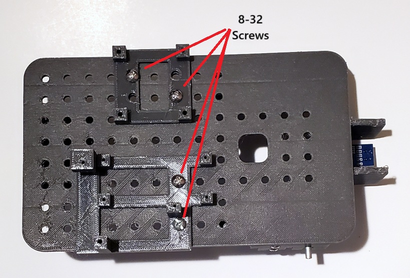
Now attach the Swivel Wheel with two or four 8-32 screws as shown:
Now mount the IR Sensor using a 2-28 screw as shown:
Now attach the Motor Controller and Raspberry Pi mounts with 8-32 screws as shown:
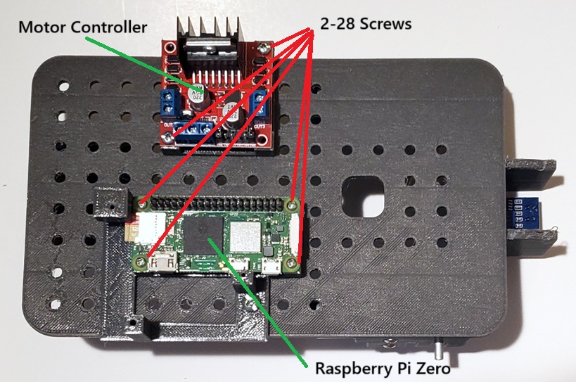
Now mount the Motor Controller and Raspberry Pi Zero with 2-28 screws as shown:
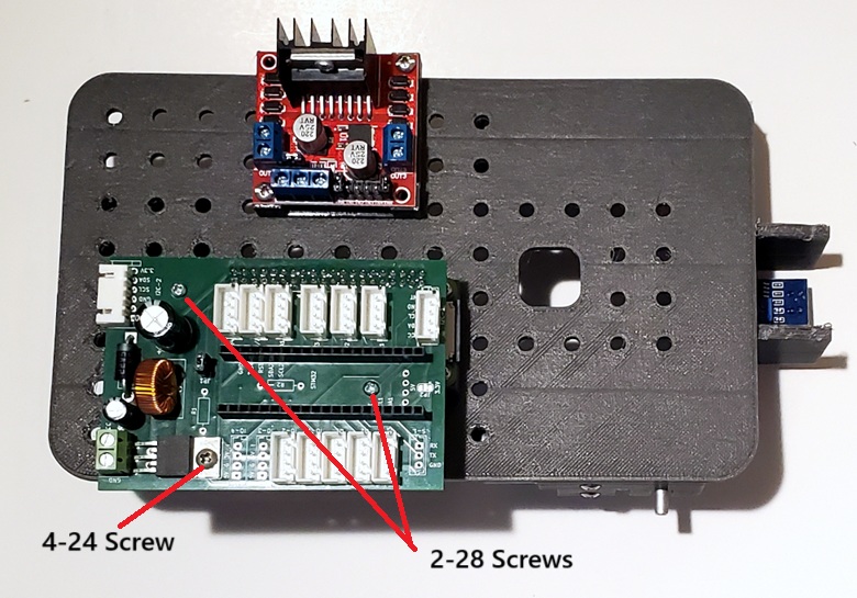
Now mount the Microcontroller Board as shown:
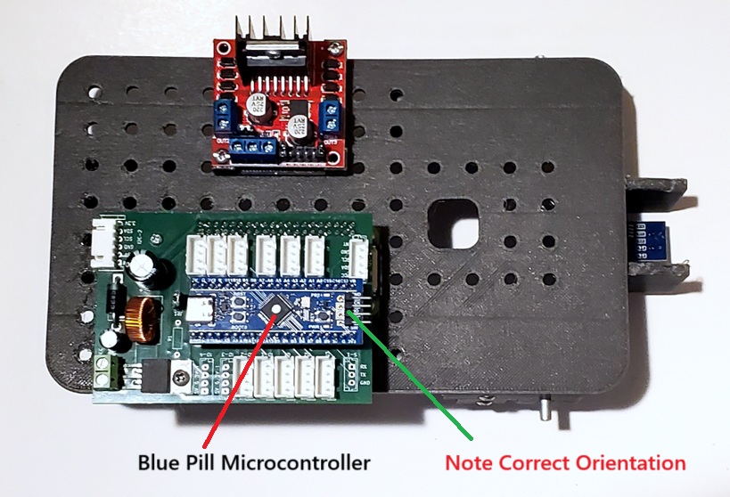
Now insert the Blue Pill Microcontroller into the socket as shown. Pay close attention to the orientation. If you plug this in backwards it WILL destroy the device (don’t ask me how I know this).
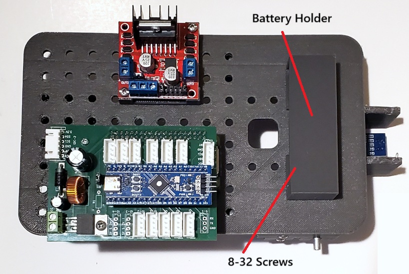
Now attach the Battery Holder using 8-32 screws as shown: