Wiring Tests
Turn the robot on and download the WiringTest program as described in the previous chapter.
This program has a number of tests that are tied to specific joystick buttons. To make things easy, we will be using the Virtual Joystick that is built into the Driver Station. To enable this feature, simply check the Enable Virtual Joystick button on the Driver Station.
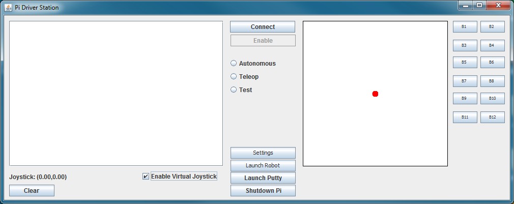
The joystick is simulated by dragging the red dot around, and the joystick buttons are simulated by pressing the buttons on the right.
To connect to the robot, press the Connect button and you should see:
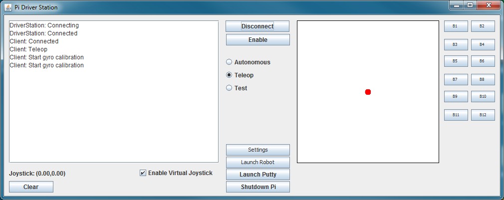
Then enable the robot by pressing the Enable button:
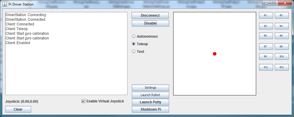
At any time, if the robot is not doing what you want, you can click the Disable button to stop it.
Test 1 – Left Motor
For the first test we will check to see that the left motor is wired correctly. If you press and hold button B1, the robot should turn to the right using only the left motor. If the left motor doesn’t run, runs backwards (i.e. the robot turns left), or the right motor runs instead of the left, then you need to check your wiring.
Test 2 – Right Motor
Next test the right motor by holding button B2. This time, the robot should turn left using only the right motor. Once again, if the right motor doesn’t run, runs backwards (i.e. the robot turns right), or the left motor runs instead of the right, then you need to check your wiring.
Test 3 – Left Encoder
In this test we are going to use button B3 to, once again, run the left motor only, but this time we are going to also print out the left encoder values. When you do this, you should see output to the Console window in Eclipse that looks something like this:
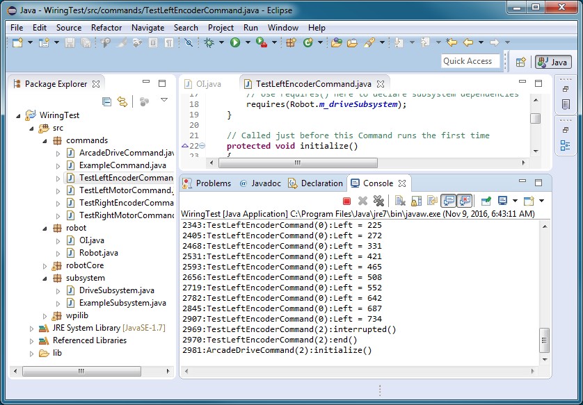
Note that the value of the left encoder is changing and increasing. If this value does not change, or does not continuously increase, then you need to check your wiring.
Test 4 – Right Encoder
In a similar manner we will test the right encoder using button B4. This should result in output which looks something like:

Once again the right encoder values should be continuously increasing.
Test 5 – Driving with a Joystick
We are now ready to drive our robot with a joystick. You can either connect a joystick to your computer of use the Virtual Joystick build into the driver station. If you decide to connect an actual joystick, you need to close the Driver Station before you connect it and then restart it. You should be able to use the joystick to move the robot forward and backwards and to turn left and right.
Test 6 – Left IR Sensor
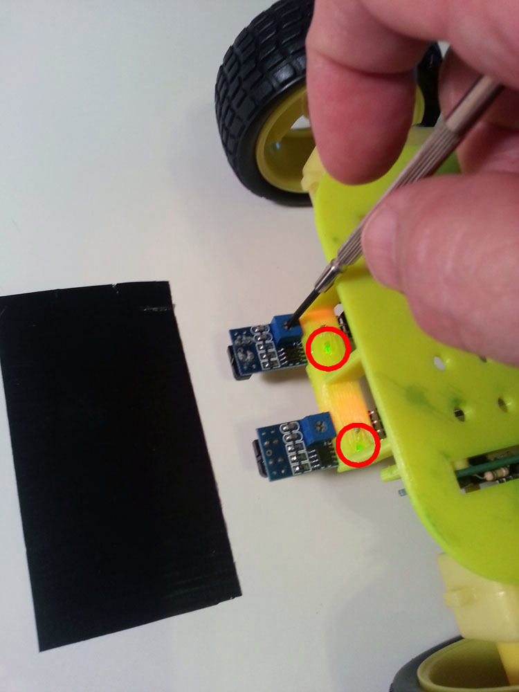
Before we run our test of the IR sensors, we need to calibrate them. Take a white sheet and add a strip of black tape. Then turn the robot on and position it so that the two IR sensors are over the white portion of the sheet. Then adjust the two little potentiometers so that the green light on the sensor comes on when the robot is over the white portion and turns off when it is over the black portion:

Now run the program and position the robot a few inches in front of the black tape. Then press button B6 and the robot should drive forward until the left IR sensor is over the black tape.
Test 7 – Right IR Sensor
Finally test the right IR sensor by once again positioning the robot a fwe inches in front of the black tape and pressing button B7 this time. As before, the robot should drive forward until the right IR sensor is over the black tape.