Encoder Board
In this chapter we are going to cover assembling the Arduino Board. The encoder board will be used to measure the rotation of the wheels. This will enable us to measure how far the robot travels as well as it’s speed.
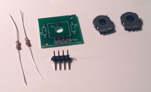
You will need the following parts.
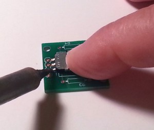
Place one of the potentiometers on the board as shown below. Hold it in place with one of your fingers and carefully solder the three connectors on the front and the one on the back. Be careful not to solder over the three holes next to the pot.
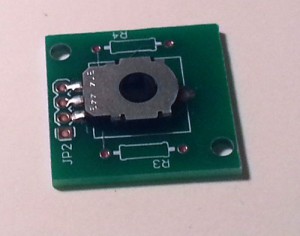
When complete it should look like:
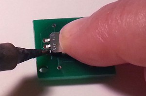
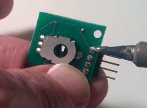
Now flip the board over and solder the second potentiometers on the reverse side in the same manner:
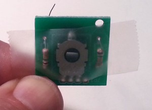
Now insert the two resisters into their proper position and hold them in place with tape:
Then flip the board over and solder them in place. After you have soldered them, cut off the excess leads.
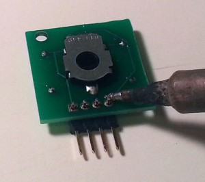
Now position the right angle header as shown below and solder only one pin:
Once that pin is soldered, pick up the board and make sure that the connector is seated properly. If it is not, you can adjust it by heating the pin you just soldered. When heating the pin, make sure that you are not touching the pin that you are heating:
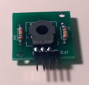
Your final board should now look like:
Repeat this process for the second encoder board.
