Wiring The Robot
The first thing we need to do is provide power for the robot. For this you will need some kind of battery. You want a battery that will deliver between 7 and 8 volts. I recommend using either a two cell LiPo battery, or six AA NiMh batteries. The wires from the battery will need to power both the Arduino/Raspberry Pi and the Motor Controller.
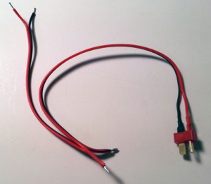
I am using a two cell LiPo battery with a ‘T’ connector and I have created a wire cable which plugs into the battery’s connector and then splits to provide power to both the Raspberry Pi and Motor Controller. The cable I created looks like this:
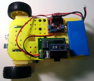
And when it is wired to the robot it looks like:
Pay careful attention to the polarity when connecting the power to the Arduino board and the motor controller. Hooking these up backwards will likely have devastating effects on your electronics.
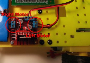
Now let’s hook up the motors. Which motor is connected to which Motor Controller output is somewhat arbitrary, as is the polarity of the connections. However, if you wish to us the tutorials of this site without change, you will need to connect the power to the motors as shown below:
Pay attention to which motor is connected to which terminal block as well as the polarities.
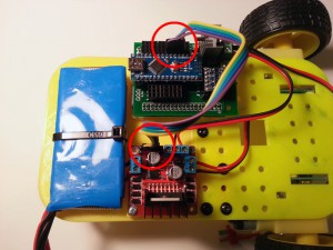
Next we need to connect the Arduino to the Motor Controller. The motor controller requires two lines to control each motor (four lines total for both motors). We will send a PWM signal to one of the lines to control the power of the motor, and use the second line to control the direction. Only some of the pins on the Arduino support PWM output and we will be using pins 3 and 5 for this purpose. For the pins that control the direction we will choose pins 4 and 6. The choice of which pins on the Arduino we connect to the four pins on the Motor Controller is somewhat arbitrary, except we must ensure that one PWM pin is used for each of the two motors. Even though we can connect the lines up in a variety of ways, if we want the motors to behave the way they do in the tutorials we will need to connect them exactly as shown below:
Pay careful attention to the orientation of the wires at the two connections if you want to use this robot with the tutorials without modifying the code.
At this point, you may want to start testing your wiring. You can wait to test after all of the wiring is completed, however, it is not a bad idea to test each piece as it is completed. If you want to start the testing now you will need work through Testing The Wiring chapter to set up your robot for programming and then work through the Left and Right motor tests in the Wiring Tests chapter
We will now connect the left wheel encoder. The encoder is a device which uses two potentiometers to measure the rotation of the wheel. These work by measuring the voltage of the center tap of the two potentiometers to determine the position of the wheel. We need to connect up one end of each potentiometer to ground and +5v. The center tap of each of the potentiometer is then connected to the analog inputs A0 and A1 of the Arduino.
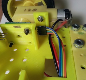
Connect a 4 pin cable to the left encoder as shown below.
Pay careful attention to how these wires are connected. It is most important to note that the second (green) and third (yellow) wires are swapped when connected to the encoder. This is necessary to have the voltage signal (green) and the data signal (yellow) applied to the correct encoder pins.
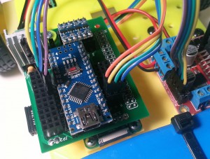
Then attach the other end of the cable to the Arduino board as shown below:
Note the placement of the connectors. The blue wire connects to the ground, the green to the +5v, the yellow to the data line of analog input 0, and the orange line to the analog input 1.
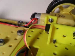
Similarly we will connect the cable for the right encoder. The connection to the encoder looks like:
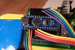
Once again note that the red and orange wires are reversed. Connecting this cable to the Arduino Board looks like:
Pay careful attention to the order of the connections. The brown wire is connected to ground, the red to +5v, the orange to analog input 2, and the yellow to analog input 3.
At this point you may want to test the encoder wiring.
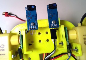
Next we will connect up the two IR Sensors. Connect 3 wires to the left IR sensor as shown below:
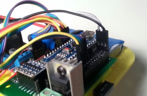
Pay careful attention to the order of the wires. In particular note that the black ground wire is swapped with the white +5v wire. Now connect those three wires to pin 13 of the Arduino.
Again, make sure you connect this in the right order as shown.
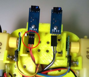
Now connect another set of three wires to the right IR sensor.
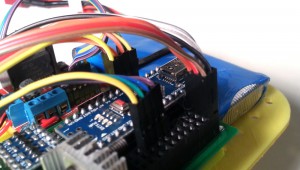
Note that the brown ground wire is swapped with the red +5v wire. Finally connect these three wires to pin 12 of the Arduino.
Your robot is now completely wired.
