In the last chapter we learned how to run our program, but it really didn’t do anything other than print logging information. That is because we have not told it to do anything yet. In this chapter we will create code which can be used to control the two drive motors.
To do this we will create a Subsystem. Subsystems are designed to control some aspect of the robot, in this case the drive motors. We are going to need to be able to control the motors using a number of different commands. Using a Subsystem lets us control what commands are allowed to access the motors, and when.”
Rather than create a new subsystem from scratch, we are going to copy the existing ExampleSubsystem and CHANGE ALL REFERENCES to ‘Example’ to our new subsystem name (that is, replace the text ‘Example’ with what we want to call it.)
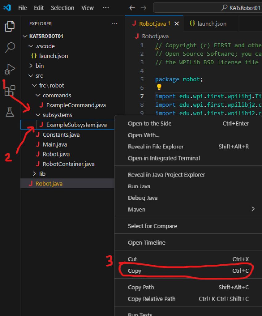
Open the subsystems folder (1) in the panel on the left. Right click on the ExampleSubsystem.java entry (2) and choose Copy (3).
Then click on the subsystems folder, right click and choose Paste.
This should result in something like this:

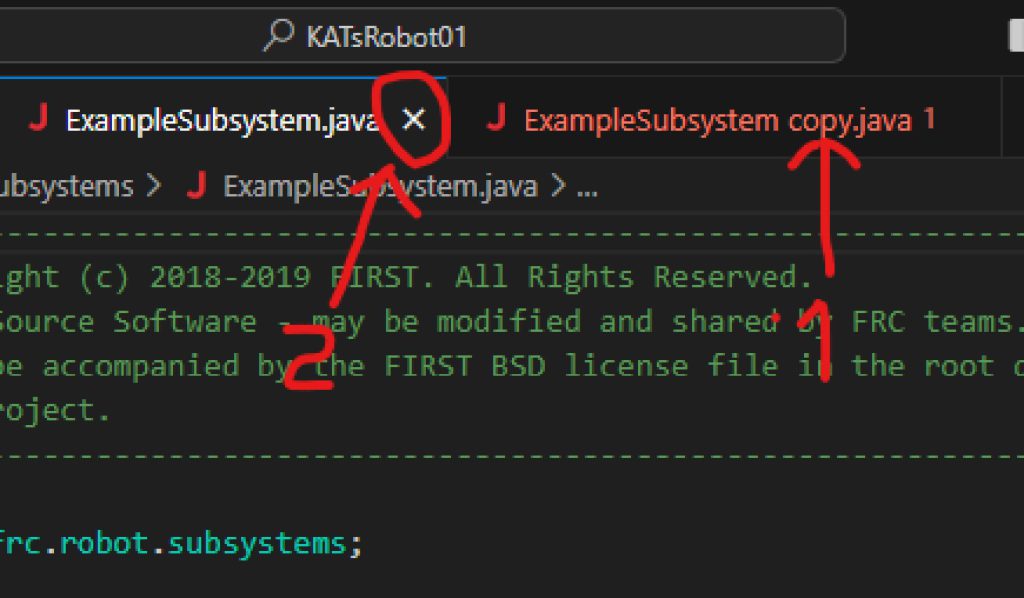
With the copy in place, we can dismiss the ExampleSubsystem.java tab (so you don’t accidently edit the original!). Don’t delete the file (left window)! We’ll need it later. But we can close the tab so we aren’t actively (and accidently!) editing it.
- (1) Make sure ExampleSubsystem-Copy.java is there and open.
- Find the ExampleSubsystem.java tab.
- Mouse-hover over it. This will show the ‘x’ at the right of the tab.
- (2) Click the ‘x’ to dismiss the window.”
Now we need to change all references of ExampleSubsystem to DriveSubsystem. This includes the filename itself*, so let’s do that first.
(*Java requires that a Class and its file have the same name. This helps Java find the right code when you import a class…and probably some other things!)
In the left window, Right Click on ‘ExampleSubsystem copy.java‘, choose Rename, and rename the file to DriveSubsystem.java.
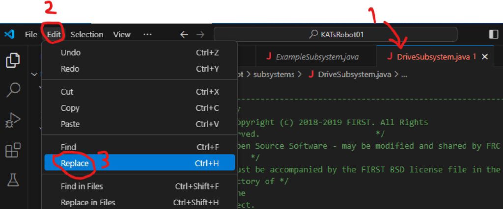
Inside the file, change them all, too. Make sure DriverSubsystem.java is selected (1) and, at the top of the VS window, click Edit (2), then Replace (3) from the drop down menu.
Then enter ExampleSubsystem as the search text and DriveSubsystem as the replacement. Then click the Replace All button.

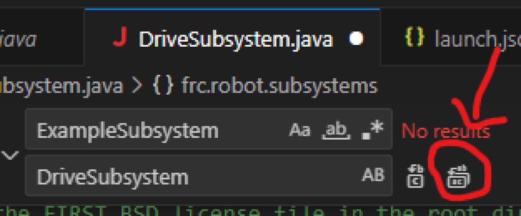
Replace All button
At this point your DriveSubsystem.java file should look like:
|
1 2 3 4 5 6 7 8 9 10 11 12 13 14 15 16 17 18 19 20 21 22 23 24 25 26 27 |
/*----------------------------------------------------------------------------*/ /* Copyright (c) 2018-2019 FIRST. All Rights Reserved. */ /* Open Source Software - may be modified and shared by FRC teams. The code */ /* must be accompanied by the FIRST BSD license file in the root directory of */ /* the project. */ /*----------------------------------------------------------------------------*/ package frc.robot.subsystems; import edu.wpi.first.wpilibj2.command.SubsystemBase; import robotCore.Logger; public class DriveSubsystem extends SubsystemBase { /** * Creates a new DriveSubsystem. */ public DriveSubsystem() { Logger.log("DriveSubsystem", 3, "DriveSubsystem()"); } @Override public void periodic() { // This method will be called once per scheduler run Logger.log("DriveSubsystem", -1, "periodic()"); } } |
This code creates a class DriveSubsystem that inherits from SubsystemBase (which was provided to us).
At the top of the class is DriveSubsystem(), the constructor. We will call this with ‘new’ later to bring our DriveSubsytem into existence (and give it a name!).
The other method in the class is periodic(). It turns out that SubsystemBase already contains a default ‘periodic()’ method. Here we override that one with the one we want for our DriveSubsystem by creating a local method with the same name. While optional, ‘@Override’ is recommended. It let’s Java know that is what we are trying to do, so if it fails (usually a spelling problem, which is quite common!) the Java compiler will let us know. Otherwise it won’t, and Java will keep the default periodic() from SubsystemBase and create whatever we told it to – our mal-named method. Debugging this is hard. (@Override is called a compiler directive. These are not technically part of the Java language, but are quite helpful to programmers.) Back to periodic()…
‘periodic‘ will be called periodically (default: every 20ms) as long as your program is running. You can use this function to perform actions that this subsystem might require. We don’t need to do anything periodically in this tutorial, so we will leave this as it is – just print a log message.
Adding Code to DriveSubsystem
If we are going to drive, we need motors and need to control them in software. WPILib includes a class for motor control called PWMMotor. To use this, we will:
- Create variables to hold the PWMMotor objects (one for each motor, left and right)
- Use these to import the correct library
- Define some variables needed to initialize the PWMMotor objects
- Create the motor objects with ‘new’
The first thing we must do, then, is to create the variables that will be used to control these motors. Add the following two lines to the top of your DriveSubsystem class (not the top of the file!):
|
1 2 |
private PWMMotor m_leftMotor; private PWMMotor m_rightMotor; |
You will note that we are prepending the variable names with an ‘m_‘ to identify them as member variables of our class. Later you will see that we also use the prefix ‘k_‘ to identify constants.
You will also note that PWMMotor is underlined in red. This means that there is an error here which must be fixed. If you hover the mouse over it you will get the notice ‘PWMMotor cannot be resolved to a type’. The problem here is that we must import the module where this class is defined. We could go to the top of the file and add the required import but there is an easier way.
If you click on one of the PWMMotor declarations and press CTRL + . (i.e. hold the CTRL key and press the period), it will give you a list of possible fixes:
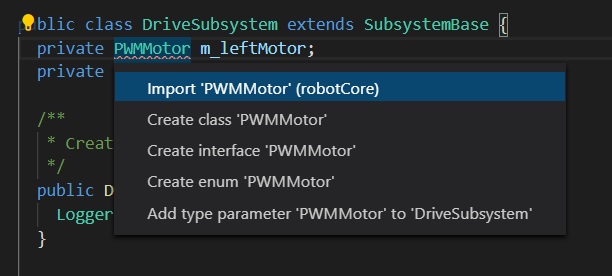
We should choose the first option.
Note that this added an import line near the top of the file:
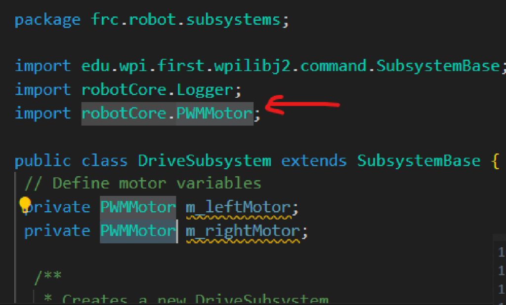
We now see that the variable names (e.g. m_leftMotor) are now underlined in yellow. The yellow underline represents a warning and while warnings will not prevent your program from running they do point to possible problems that may need to be fixed. In this case if we hover over the warning we will see the message ‘The value of the field DriveSubsystem.m_leftMotor is not used’. This is ok at this time since we will be adding code which will use these fields and the warning will go away. In general, you should try and eliminate all warnings from your program. If you have a warning that you know that you want to ignore you can make it go away using the @SuppressWarnings directive. You should, of course, only suppress warnings that you know for a fact are not going to cause problems.
We have declared the variables to control the motors, but we still need to initialize them. We need to be careful when we create the instances of these controllers. When writing code to control hardware, you cannot expect to be able to communicate with that hardware before the robot is initialized so we must make sure that the motor classes are not instantiated until the robot code has been initialized. However, if we wait to create an instance of this class until the robot is initialized, then it will be safe to initialize these variable in this class’s constructor.
Looking at the documentation for PWMMotor we see the constructor requires 2 integers, a pwmPin and a dirPin. The first pin will control the power of the motor and the second will control the direction. We are using a microcontroller to provide these signals and only some of the pins can be configured for PWM (Pulse Width Modulation) output. To control the power we will be using pin Device.M1_1_PWM for the right motor and pin Device.M1_2_PWM for the left motor. To control the direction, we will be using pin Device.M1_1_DIR for the right motor and pin Device.M1_2_DIR for the left. Given this, we can call the PWMMotor() constructor to instantiate our PWMMotor objects, and initialize our motor variables with them by adding to the declarations we already wrote:
|
1 2 3 4 5 6 7 8 |
private static final int k_leftMotorPWMPin = Device.M1_2_PWM; private static final int k_leftMotorDirPin = Device.M1_2_DIR; private static final int k_rightMotorPWMPin = Device.M1_1_PWM; private static final int k_rightMotorDirPin = Device.M1_1_DIR; private PWMMotor m_leftMotor = new PWMMotor(k_leftMotorPWMPin, k_leftMotorDirPin); private PWMMotor m_rightMotor = new PWMMotor(k_rightMotorPWMPin, k_rightMotorDirPin); |
Note that motor variables are used in the PWMMotor constructors, so these must already be defined. In this case, it means they need to come first in the file.
You will, of course, also need to import Device from RobotCore;
|
1 |
import robotCore.Device; |
Now that we have defined and initialized the variables that control the motors we need to provide a function that will allow users of this class the ability to set the power on the motors. We will create a function called setPower which will allow us to set the power of the left and right motors. Once again consulting the documentation for PWMMotor we find that we can set the power on an individual motor by calling its set(double power) function. This function takes a single argument which specifies the power and can range from -1.0 for full reverse to +1.0 for full forward. Given this we will define our setPower function as follows.
Because Constructors come before methods in a class, setPower() goes after DriveSubsystem(), but can come before periodic().
|
1 2 3 4 |
public void setPower(double leftPower, double rightPower) { m_rightMotor.set(rightPower); m_leftMotor.set(leftPower); } |
Note that there will be many cases where you will want to stop the motor. You can, of course, call setPower(0, 0) but you could also create a function called stop() which will do that.
Your DriveSubsystem.java file should now look like:
|
1 2 3 4 5 6 7 8 9 10 11 12 13 14 15 16 17 18 19 20 21 22 23 24 25 26 27 28 29 30 31 32 33 34 35 36 37 38 39 40 41 42 43 44 45 46 47 48 49 |
/*----------------------------------------------------------------------------*/ /* Copyright (c) 2018-2019 FIRST. All Rights Reserved. */ /* Open Source Software - may be modified and shared by FRC teams. The code */ /* must be accompanied by the FIRST BSD license file in the root directory of */ /* the project. */ /*----------------------------------------------------------------------------*/ package frc.robot.subsystems; import edu.wpi.first.wpilibj2.command.SubsystemBase; import robotCore.Device; import robotCore.Logger; import robotCore.PWMMotor; public class DriveSubsystem extends SubsystemBase { //Define motor constructor arguments before Constructor calls private static final int k_leftMotorPWMPin = Device.M1_2_PWM; private static final int k_leftMotorDirPin = Device.M1_2_DIR; private static final int k_rightMotorPWMPin = Device.M1_1_PWM; private static final int k_rightMotorDirPin = Device.M1_1_DIR; // Define motor variables //and Instantiate and assign PWMMotor objects, left and right private PWMMotor m_leftMotor = new PWMMotor(k_leftMotorPWMPin, k_leftMotorDirPin); private PWMMotor m_rightMotor = new PWMMotor(k_rightMotorPWMPin, k_rightMotorDirPin); /** * Creates a new DriveSubsystem. */ public DriveSubsystem() { Logger.log("DriveSubsystem", 3, "DriveSubsystem()"); } //Sets the power for the motors. //Sets both motors to the same power. // leftPower & rightPower are -1.0 (full rev) to 1.0 (full fwd) public void setPower(double leftPower, double rightPower) { m_rightMotor.set(rightPower); m_leftMotor.set(leftPower); } @Override public void periodic() { // This method will be called once per scheduler run Logger.log("DriveSubsystem", -1, "periodic()"); } } |