Now that we know how to use the encoders, we want to change our DriveSubsystem class so that we can set the motors to run at a specific speed by automatically adjusting the power of the motors to maintain that speed.
Before we tackle that, however, we need to gather some information as to the relationship between the power applied to the motors and their speed. We are going to create a new command where we will run the robot forward at different power settings and record the speed that results.
Start by adding a new class TestMotorSpeedCommand to the commands folder, and copy the contents of ExampleCommand.java replacing the ExampleCommand and ExampleSubsystem strings. Your result should look like:
|
1 2 3 4 5 6 7 8 9 10 11 12 13 14 15 16 17 18 19 20 21 22 23 24 25 26 27 28 29 30 31 32 33 34 35 36 37 38 39 40 41 42 43 44 45 46 47 48 49 50 51 52 53 54 55 56 57 58 |
/*----------------------------------------------------------------------------*/ /* Copyright (c) 2018-2019 FIRST. All Rights Reserved. */ /* Open Source Software - may be modified and shared by FRC teams. The code */ /* must be accompanied by the FIRST BSD license file in the root directory of */ /* the project. */ /*----------------------------------------------------------------------------*/ package frc.robot.commands; import edu.wpi.first.wpilibj2.command.Command; import frc.robot.subsystems.DriveSubsystem; import robotCore.Logger; /** * An example command that uses an example subsystem. */ public class TestMotorSpeedCommand extends Command { private final DriveSubsystem m_subsystem; /** * Creates a new TestMotorSpeedCommand. * * @param subsystem The subsystem used by this command. */ public TestMotorSpeedCommand(DriveSubsystem subsystem) { Logger.log("TestMotorSpeedCommand", 3, "TestMotorSpeedCommand()"); m_subsystem = subsystem; // Use addRequirements() here to declare subsystem dependencies. addRequirements(m_subsystem); } // Called when the command is initially scheduled. @Override public void initialize() { Logger.log("TestMotorSpeedCommand", 2, "initialize()"); } // Called every time the scheduler runs while the command is scheduled. @Override public void execute() { Logger.log("TestMotorSpeedCommand", -1, "execute()"); } // Called once the command ends or is interrupted. @Override public void end(boolean interrupted) { Logger.log("TestMotorSpeedCommand", 2, String.format("end(%b)", interrupted)); } // Returns true when the command should end. @Override public boolean isFinished() { Logger.log("TestMotorSpeedCommand", -1, "isFinished()"); return false; } } |
Now what we want to do is to start the robot at 0 power and gradually increase the power, recording the speed, until we reach full power. To accomplish this we need to create a member variable m_power to hold the current power setting. We are also going to want to record the speed of the motors so we will need an Encoder instance for the left and right encoders.
|
1 2 3 4 5 6 7 8 9 10 11 12 13 14 15 16 17 18 19 20 21 22 23 24 25 26 27 28 29 30 31 32 33 34 35 36 37 38 39 40 41 42 43 44 45 |
/*----------------------------------------------------------------------------*/ /* Copyright (c) 2018-2019 FIRST. All Rights Reserved. */ /* Open Source Software - may be modified and shared by FRC teams. The code */ /* must be accompanied by the FIRST BSD license file in the root directory of */ /* the project. */ /*----------------------------------------------------------------------------*/ package frc.robot.commands; import edu.wpi.first.wpilibj2.command.Command; import frc.robot.subsystems.DriveSubsystem; import robotCore.Encoder; import robotCore.Logger; /** * An example command that uses an example subsystem. */ public class TestMotorSpeedCommand extends Command { private final DriveSubsystem m_subsystem; //Current power private double m_power; //Encoder objects, left and right private final Encoder m_leftEncoder; private final Encoder m_rightEncoder; /** * Creates a new TestMotorSpeedCommand. * * @param subsystem The subsystem used by this command. */ public TestMotorSpeedCommand(DriveSubsystem subsystem) { Logger.log("TestMotorSpeedCommand", 3, "TestMotorSpeedCommand()"); m_subsystem = subsystem; m_leftEncoder = subsystem.getLeftEncoder(); m_rightEncoder = subsystem.getRightEncoder(); // Use addRequirements() here to declare subsystem dependencies. addRequirements(m_subsystem); } |
As we’ve seen before, we declare the class variables right after class command to reserve these names for Encoder objects, then in the constructor we get the left and right Encoder objects from the subsystem, and assign them to our class variables. This gives access to the Encoder objects to every method in this class.
In the initialize() function we need to set the power to 0. Also we will be logging the motor speeds in the execute() function in a format that will allow us to import them into a spreadsheet. To make the spreadsheet easier to read we add a title row which labels each column.
|
1 2 3 4 5 6 7 8 |
public void initialize() { Logger.log("TestMotorSpeedCommand", 2, "initialize()"); //Write header for power data in log Logger.log("TestMotorSpeedCommand", 0, ",Power,Left,Right"); m_power = 0; } |
Then in the execute() function we will set the drive power to the current power and then increase the power by 0.0025 each time we are called. We will use the getSpeed() function of the Encoder class and Logger.log() to log the speeds of the two motors so that we can view them later. To accomplish this we change the execute() function as follows:
|
1 2 3 4 5 6 7 8 9 10 |
public void execute() { Logger.log("TestMotorSpeedCommand", -1, "execute()"); Logger.log("TestMotorSpeedCommand", 0, String.format(",%f,%d,%d", m_power, m_leftEncoder.getSpeed(), m_rightEncoder.getSpeed())); m_subsystem.setPower(m_power, m_power); m_power += 0.0025; } |
Note that we do not need to put these in a for loop, since execute is called periodically by the WPILib framework, so we get it for free!
Then we need to change the isFinished() function to return true when the power exceeds 1.3. Note that we are increasing the power up to 1.3 even though the highest power the motor will accept is 1.0 (anything over that will be treated the same as 1.0). The reason we are doing this is to see exactly where the speed tops out.
|
1 2 3 4 |
public boolean isFinished() { Logger.log("TestMotorSpeedCommand", -1, "isFinished()"); return m_power > 1.3; } |
Finally when the command is finished, we need to turn the motors off.
|
1 2 3 4 5 6 7 |
public void end(boolean interrupted) { Logger.log("TestMotorSpeedCommand", 2, String.format("end(%b)", interrupted)); //All done. Turn off the motors. m_subsystem.setPower(0, 0); } |
Your TestMotorSpeedCommand.java file should now look like:
|
1 2 3 4 5 6 7 8 9 10 11 12 13 14 15 16 17 18 19 20 21 22 23 24 25 26 27 28 29 30 31 32 33 34 35 36 37 38 39 40 41 42 43 44 45 46 47 48 49 50 51 52 53 54 55 56 57 58 59 60 61 62 63 64 65 66 67 68 69 70 71 72 73 74 75 76 77 78 79 80 81 82 83 84 85 |
/*----------------------------------------------------------------------------*/ /* Copyright (c) 2018-2019 FIRST. All Rights Reserved. */ /* Open Source Software - may be modified and shared by FRC teams. The code */ /* must be accompanied by the FIRST BSD license file in the root directory of */ /* the project. */ /*----------------------------------------------------------------------------*/ package frc.robot.commands; import edu.wpi.first.wpilibj2.command.Command; import frc.robot.subsystems.DriveSubsystem; import robotCore.Encoder; import robotCore.Logger; /** * An example command that uses an example subsystem. */ public class TestMotorSpeedCommand extends Command { private final DriveSubsystem m_subsystem; //Current power private double m_power; //Encoder objects, left and right private final Encoder m_leftEncoder; private final Encoder m_rightEncoder; /** * Creates a new TestMotorSpeedCommand. * * @param subsystem The subsystem used by this command. */ public TestMotorSpeedCommand(DriveSubsystem subsystem) { Logger.log("TestMotorSpeedCommand", 3, "TestMotorSpeedCommand()"); m_subsystem = subsystem; m_leftEncoder = subsystem.getLeftEncoder(); m_rightEncoder = subsystem.getRightEncoder(); // Use addRequirements() here to declare subsystem dependencies. addRequirements(m_subsystem); } // Called when the command is initially scheduled. @Override public void initialize() { Logger.log("TestMotorSpeedCommand", 2, "initialize()"); //Write header for power data in log Logger.log("TestMotorSpeedCommand", 0, ",Power,Left,Right"); m_power = 0; } // Called every time the scheduler runs while the command is scheduled. @Override public void execute() { Logger.log("TestMotorSpeedCommand", -1, "execute()"); Logger.log("TestMotorSpeedCommand", 0, String.format(",%f,%d,%d", m_power, m_leftEncoder.getSpeed(), m_rightEncoder.getSpeed())); m_subsystem.setPower(m_power, m_power); m_power += 0.0025; } // Called once the command ends or is interrupted. @Override public void end(boolean interrupted) { Logger.log("TestMotorSpeedCommand", 2, String.format("end(%b)", interrupted)); //All done. Turn off the motors. m_subsystem.setPower(0, 0); } // Returns true when the command should end. @Override public boolean isFinished() { Logger.log("TestMotorSpeedCommand", -1, "isFinished()"); return m_power > 1.3; } } |
Finally need to have a button on the joystick that will run this command. Switching to the RobotContainer.java file, we configure it to run our TestMotorSpeedCommand when button 3 is pressed:
|
1 2 3 4 5 6 7 8 9 10 11 |
/** * Use this method to define your button->command mappings. Buttons can be * created by instantiating a {@link GenericHID} or one of its subclasses * ({@link edu.wpi.first.wpilibj.Joystick} or {@link XboxController}), and then * passing it to a {@link edu.wpi.first.wpilibj2.command.button.JoystickButton}. */ private void configureButtonBindings() { m_joystick.button(1).onTrue(new DriveForTimeCommand(m_driveSubsystem, 0.50, 3.0)); m_joystick.button(2).onTrue(new DriveForDistanceCommand(m_driveSubsystem, 0.75, 2000)); m_joystick.button(3).onTrue(new TestMotorSpeedCommand(m_driveSubsystem)); } |
Now run your program and connect and enable your robot. Before pressing the B3 button to run our command we want to clear the TERMINAL in VS Code.
Unfortunately the only way I have found to do that is a little bit convoluted (A possibly simpler way is at the bottom of this section, but doesn’t include Select All, which we’ll need later!). First right click on the word TERMINAL at the bottom of the screen. This will bring up the following menu:
Now ignore this menu and without closing it move the cursor down to the TERMINAL area and right click. This should then give you the menu:
Choose the Clear option from this menu.
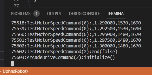
Now press the B3 button on the Driver Station. The robot should drive forward slowly increasing it speed. When it has stopped, the logged information should be in the TERMINAL pane:
Now we want to select all of the text in this window so we can paste it into our spreadsheet. Unfortunately using the normal Windows shortcut CTRL + a does not seem to work for some reason. However we can us the same trick that we used to clear the TERMINAL. First right click on the word TERMINAL. Then, ignoring that menu, right click on the TERMINAL window and choose Select All. Then repeat this procedure and this time choose Copy.
Now that you have the text copied to the clipboard start up LibreOffice Calc. Then choose Edit / Paste and you should get the following dialog:

Make sure the Comma option is checked under the Separator Options and then click OK.
Then select the Power, Left and Right columns (i.e. D, E and F):

and click the Insert Chart icon at the top:

For the chart type choose the XY (Scatter) and Lines Only options as shown below:

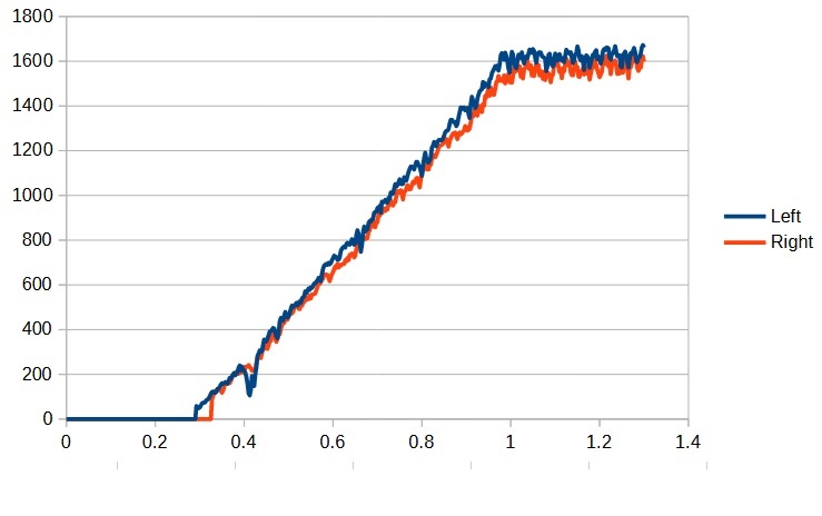
Now there are two different Minibots, one which uses metal motors and one that uses blue motors and they have different characteristics. Below are the results from the two types and you should compare your results to the type that you are using. Note that in the following discussions we will be noting the blue motor values using the blue color.
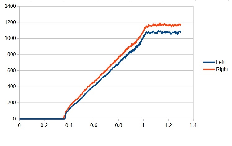
This is a plot of the motor speed vs the power applied. There are several things we can see from looking at the graph.
Note that these are the results for this particular robot. Your robot may differ and you should adjust these numbers accordingly.
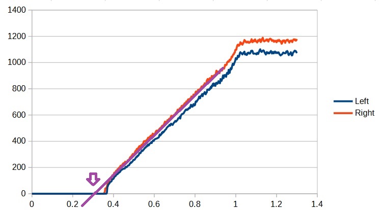
The first is that the motors will not even start running until the power reaches about 0.3 and tops out when the power reaches 1.0 (a power of 1.0 represents running the motor at full power). The second is that the left motor is less powerful than the right which is the reason the robot turns left. The last takeaway is that the max speed for the right motor is about 1175 (1580) and the max speed of the left motor is about 1075 (1620). If we want the robot to drive straight then the max speed for the whole robot will need to be limited to the slower motor (i.e. 1075 (1580)). So let’s define a constant for that max speed (in DriveSubsystem):
|
1 2 3 |
//Define motor-specific constants public static final double k_maxSpeed = 1075; // public static final double k_maxSpeed = 1580; // For the blue motor |
Note that we have made k_maxSpeed public here. This is so we can later use it to log the target speed in the units of the encoders.
Note that these are the results for this particular robot. Your robot may differ and you should adjust these numbers accordingly.
PID Controllers, and How to Tune Them
Our PWMMotor class inherits (outside of our code) from the SmartMotor class. SmartMotor has a way to map a requested motor speed to a motor power. Using this, our code only needs to be concerned with speed, and let SmartMotor command the motors yield that speed. That’s the good news, since we understand robot speed and want to use that in our planning and our code, and not worry about how that happens. Yep, that’s the good news.
The bad news is that we need to tune SmartMotor‘s algorithm with specific values for our motors, so there’s some work to be done up front. Details…
The SmartMotor class controls the speed of the motor using a PID controller. PID stands for Proportional, Integral, Differential. When we use this control mechanism, we will set a target for the speed we desire (called the setPoint) and the SmartMotor class will adjust the power sent to the motor based on the following formula:
|
1 |
power = (P * error) + (I * totalError) + (D * deltaError) + (F * setPoint) |
where
- P – represents the proportional scale factor.
- error – represents the difference between the current speed and the setPoint.
- I – represents the integral scale factor.
- totalError – represents the total accumulated error over time.
- D – represents the derivative scale factor.
- deltaError – represents the difference between the current error and the last.
- F – represents the constant scale factor which is proportional to the setPoint.
- setPoint – represents the current target speed.
The trick is picking the right combination of P, I, D and F to make the motor behave like you want. Here’s how:
We will start with the F term which represents a constant power which proportional to the setPoint. Now we know (from our graph…change the numbers below for your graph) that at full power the maximum speed of the right motor is about maxSpeed (1175 or 1580) units/sec. Thus we need an F term that, when multiplied by the max speed will result in full power being applied (i.e. a power of 1.0). That number is 1.0/maxSpeed.
Note that setting only the constant term, F, is essentially the same as controlling the motor by power alone. No adjustments will occur if there is more or less resistance to the motors, and the motors will slow down or speed up. However, we want to get this term set so that the motors run close to the target speed we desire.
The first thing we need to do however is to tell the motor controller about the motors’ minimum power requirements. We do this by calling setMinPower in the DriveSubsystem constructor.
|
1 2 |
m_leftMotor.setMinPower(k_minPowerLeft); m_rightMotor.setMinPower(k_minPowerRight); |
Where we have defined:
|
1 2 |
private static final double k_minPowerLeft = 0.3; private static final double k_minPowerRight = 0.3; |
For the minimum value, we choose the point at which the linear portion of the graph would intersect the x axis. In this case it about 0.3 for both motors.
Next we set the F terms, by calling setFTerm in the DriveSubsystem constructor:
|
1 2 |
m_leftMotor.setFTerm(k_Fleft); m_rightMotor.setFTerm(k_Fright); |
Where we have defined:
|
1 2 |
private static final double k_Fleft = 1.0/k_maxSpeed; private static final double k_Fright = 1.0/k_maxSpeed; |
In order for the motor controller to control the speed of the motors, it will need to know what encoders are being used to measure the speed. We set that by calling setFeedbackDevice() for the motors in the DriveSubsystem constructor as follows:
|
1 2 |
m_leftMotor.setFeedbackDevice(m_leftEncoder); m_rightMotor.setFeedbackDevice(m_rightEncoder); |
Next we want to set a scale factor so when we want to set the speed, we can just use a range from -1.0 to +1.0 (like we do when controlling the motors by power). Otherwise we would need to set the speed based on the arbitrary units of the encoder which is cumbersome and not intuitive. We do this by calling setMaxSpeed in the constructor:
|
1 2 |
m_leftMotor.setMaxSpeed(k_maxSpeed); m_rightMotor.setMaxSpeed(k_maxSpeed); |
Finally, we could change the setPower function of our DriveSubsystem class to set the speed instead of power, but there may be a time in the future where we still want to control the power. Therefore, we will create a new function setSpeed which we will use to set the speed as follows:
|
1 2 3 4 5 6 7 8 |
//Sets the speed for the motors public void setSpeed(double leftSpeed, double rightSpeed) { m_leftMotor.setControlMode(SmartMotorMode.Speed); m_rightMotor.setControlMode(SmartMotorMode.Speed); m_leftMotor.set(leftSpeed); m_rightMotor.set(rightSpeed); } |
Note that we must ensure that the controller is in speed mode (not power mode) by calling the setControlMode function. Then we set the desired speeds.
We also need to change the setPower function to set the control mode back to power by adding the following to setPower:
|
1 2 3 4 5 6 7 8 9 10 11 |
public void setPower(double leftPower, double rightPower) { //Sets the power for the motors. //Sets both motors to the same power. // leftPower & rightPower are -1.0 (full rev) to 1.0 (full fwd) public void setPower(double leftPower, double rightPower) { m_leftMotor.setControlMode(SmartMotorMode.Power); m_rightMotor.setControlMode(SmartMotorMode.Power); m_rightMotor.set(rightPower); m_leftMotor.set(leftPower); } |
Your DriveSubsystem.java file should now look something like:
|
1 2 3 4 5 6 7 8 9 10 11 12 13 14 15 16 17 18 19 20 21 22 23 24 25 26 27 28 29 30 31 32 33 34 35 36 37 38 39 40 41 42 43 44 45 46 47 48 49 50 51 52 53 54 55 56 57 58 59 60 61 62 63 64 65 66 67 68 69 70 71 72 73 74 75 76 77 78 79 80 81 82 83 84 85 86 87 88 89 90 91 92 93 94 95 96 97 98 99 100 101 102 103 104 105 106 107 108 109 110 111 |
/*----------------------------------------------------------------------------*/ /* Copyright (c) 2018-2019 FIRST. All Rights Reserved. */ /* Open Source Software - may be modified and shared by FRC teams. The code */ /* must be accompanied by the FIRST BSD license file in the root directory of */ /* the project. */ /*----------------------------------------------------------------------------*/ package frc.robot.subsystems; import edu.wpi.first.wpilibj2.command.SubsystemBase; import robotCore.Device; import robotCore.Encoder; import robotCore.Logger; import robotCore.PWMMotor; import robotCore.SmartMotor.SmartMotorMode; public class DriveSubsystem extends SubsystemBase { //Define motor constructor arguments before Constructor calls private static final int k_leftMotorPWMPin = Device.M1_2_PWM; private static final int k_leftMotorDirPin = Device.M1_2_DIR; private static final int k_rightMotorPWMPin = Device.M1_1_PWM; private static final int k_rightMotorDirPin = Device.M1_1_DIR; //Define encoder constructor argumatns before Constrctor calls private static final int k_leftEncoderPin1 = Device.Q1_INT; private static final int k_leftEncoderPin2 = Device.Q1_DIR; private static final int k_rightEncoderPin1 = Device.Q2_INT; private static final int k_rightEncoderPin2 = Device.Q2_DIR; //Define motor-specific constants private static final double k_minPowerLeft = 0.3; private static final double k_minPowerRight = 0.3; public static final double k_maxSpeed = 1075; // public static final double k_maxSpeed = 1580; // For the blue motor //PID values private static final double k_Fleft = 1.0/k_maxSpeed; private static final double k_Fright = 1.0/k_maxSpeed; // Define motor variables //and Instantiate and assign PWMMotor objects, left and right private PWMMotor m_leftMotor = //From before new PWMMotor(k_leftMotorPWMPin, k_leftMotorDirPin); //added this private PWMMotor m_rightMotor = //From before new PWMMotor(k_rightMotorPWMPin, k_rightMotorDirPin); //added this //Instantiate and assign Encoder objtects, left and right. private Encoder m_leftEncoder = new Encoder(robotCore.Encoder.EncoderType.Quadrature, k_leftEncoderPin1, k_leftEncoderPin2); private Encoder m_rightEncoder = new Encoder(robotCore.Encoder.EncoderType.Quadrature, k_rightEncoderPin1, k_rightEncoderPin2); /** * Creates a new DriveSubsystem. */ public DriveSubsystem() { Logger.log("DriveSubsystem", 3, "DriveSubsystem()"); m_leftMotor.setFeedbackDevice(m_leftEncoder); m_rightMotor.setFeedbackDevice(m_rightEncoder); m_leftMotor.setMaxSpeed(k_maxSpeed); m_rightMotor.setMaxSpeed(k_maxSpeed); m_leftMotor.setMinPower(k_minPowerLeft); m_rightMotor.setMinPower(k_minPowerRight); m_leftMotor.setFTerm(k_Fleft); m_rightMotor.setFTerm(k_Fright); m_rightEncoder.setInverted(true); } //Sets the power for the motors. //Sets both motors to the same power. // leftPower & rightPower are -1.0 (full rev) to 1.0 (full fwd) public void setPower(double leftPower, double rightPower) { m_leftMotor.setControlMode(SmartMotorMode.Power); m_rightMotor.setControlMode(SmartMotorMode.Power); m_rightMotor.set(rightPower); m_leftMotor.set(leftPower); } //Sets the speed for the motors public void setSpeed(double leftSpeed, double rightSpeed) { m_leftMotor.setControlMode(SmartMotorMode.Speed); m_rightMotor.setControlMode(SmartMotorMode.Speed); m_leftMotor.set(leftSpeed); m_rightMotor.set(rightSpeed); } //Return the left encoder value public Encoder getLeftEncoder() { return (m_leftEncoder); } //Return the right encoder value public Encoder getRightEncoder() { return (m_rightEncoder); } @Override public void periodic() { // This method will be called once per scheduler run Logger.log("DriveSubsystem", -1, "periodic()"); } } |
Next we want to add a new command that we can use to test out our speed control. Create a new class under the commands folder called CalibrateSpeedCommand and, as before:
- Copy over the code from ExampleCommand
- Rename the the .java file.
- Replace ExampleCommand.
- Replace ExampleSubsystem
Now for this test, we are simply going to run the robot at a constant speed and log the results so that we can see how close to that speed we come. Since we will be logging the motor speeds, we will need access to the left and right encoders so we declare member variables to hold those values, create the Encoder import, and initialize them in the constructor:
|
1 2 3 4 5 6 7 8 9 10 11 12 13 14 15 16 |
/** * Creates a new CalibrateSpeedCommand. * * @param subsystem The subsystem used by this command. */ public CalibrateSpeedCommand(DriveSubsystem subsystem) { Logger.log("CalibrateSpeedCommand", 3, "CalibrateSpeedCommand()"); m_subsystem = subsystem; m_leftEncoder = m_subsystem.getLeftEncoder(); m_rightEncoder = m_subsystem.getRightEncoder(); // Use addRequirements() here to declare subsystem dependencies. addRequirements(m_subsystem); } |
In the initialize() function we will simply use our new setSpeed(…) function to start the robot forward at 0.75 speed. Since we will also be logging the speed, we log the title row for our CSV file. Note the placement of the comma right before “Target Speed”. We need this so that it will be formatted in a way that we can easily import it into the spreadsheet.
|
1 2 3 4 5 6 7 8 9 10 |
// Called when the command is initially scheduled. @Override public void initialize() { Logger.log("TestSpeedControlCommand", 2, "initialize()"); Logger.log("TestSpeedControlCommand", 3, "...,Target Speed,Left Speed, Right Speed"); m_subsystem.setSpeed(k_speed, k_speed); } |
Note we are using k_speed, but haven’t defined it in this class yet! Add the definition with the class variable, giving it an initial value of 0.75.
In the execute() function we want to log the current time, power, and speeds of the two motors. Once again. note the comma that precedes the “%.0f,…” string.
|
1 2 3 4 5 6 7 8 |
// Called every time the scheduler runs while the command is scheduled. @Override public void execute() { Logger.log("CalibrateSpeedCommand", -1, "execute()"); Logger.log("TestSpeedControl", 3, String.format(",%.0f,%d,%d", k_speed * DriveSubsystem.k_maxSpeed, m_leftEncoder.getSpeed(), m_rightEncoder.getSpeed())); } |
Note that we are also logging the target speed and we need to multiply k_speed by the k_maxSpeed defined in the DriveSubsystem so that the units will match those returned by the encoder’s getSpeed() function.
We are going to make this command run as long as we hold down joystick button 4, and stop when we release it. This way of stopping execution is handled when we register our command with joystick button 4 (we get to it below), and does not rely on the isFinished() function. So we just want isFinished() to return false. This is the default from ExampleCommand, so no changes are needed.
When we release button 4 on the joystick, the command will be interrupted and it’s end() function will be called. At that point we need to turn the motors off.
|
1 2 3 4 5 6 7 8 |
// Called once when the command ends or is interrupted. @Override public void end(boolean interrupted) { Logger.log("CalibrateSpeedCommand", 2, String.format("end(%b)", interrupted)); m_subsystem.setPower(0, 0); } |
Your CalibrateSpeedCommand.java should now look like:
|
1 2 3 4 5 6 7 8 9 10 11 12 13 14 15 16 17 18 19 20 21 22 23 24 25 26 27 28 29 30 31 32 33 34 35 36 37 38 39 40 41 42 43 44 45 46 47 48 49 50 51 52 53 54 55 56 57 58 59 60 61 62 63 64 65 66 67 68 69 70 71 72 73 74 75 |
/*----------------------------------------------------------------------------*/ /* Copyright (c) 2018-2019 FIRST. All Rights Reserved. */ /* Open Source Software - may be modified and shared by FRC teams. The code */ /* must be accompanied by the FIRST BSD license file in the root directory of */ /* the project. */ /*----------------------------------------------------------------------------*/ package frc.robot.commands; import edu.wpi.first.wpilibj2.command.Command; import frc.robot.subsystems.DriveSubsystem; import robotCore.Encoder; import robotCore.Logger; /** * Calibrates the speed by setting the F, P, I and IZone values. */ public class CalibrateSpeedCommand extends Command { private final DriveSubsystem m_subsystem; private final double k_speed = 0.75; private Encoder m_leftEncoder; private Encoder m_rightEncoder; /** * Creates a new CalibrateSpeedCommand. * * @param subsystem The subsystem used by this command. */ public CalibrateSpeedCommand(DriveSubsystem subsystem) { Logger.log("CalibrateSpeedCommand", 3, "CalibrateSpeedCommand()"); m_subsystem = subsystem; m_leftEncoder = m_subsystem.getLeftEncoder(); m_rightEncoder = m_subsystem.getRightEncoder(); // Use addRequirements() here to declare subsystem dependencies. addRequirements(m_subsystem); } // Called when the command is initially scheduled. @Override public void initialize() { Logger.log("CalibrateSpeedCommand", 2, "initialize()"); Logger.log("TestSpeedControlCommand", 3, "...,Target Speed,Left Speed, Right Speed"); m_subsystem.setSpeed(k_speed, k_speed); } // Called every time the scheduler runs while the command is scheduled. @Override public void execute() { Logger.log("CalibrateSpeedCommand", -1, "execute()"); Logger.log("TestSpeedControl", 3, String.format(",%.0f,%d,%d", k_speed * DriveSubsystem.k_maxSpeed, m_leftEncoder.getSpeed(), m_rightEncoder.getSpeed())); } // Called once when the command ends or is interrupted. @Override public void end(boolean interrupted) { Logger.log("CalibrateSpeedCommand", 2, String.format("end(%b)", interrupted)); m_subsystem.setPower(0, 0); } // Returns true when the command should end. @Override public boolean isFinished() { Logger.log("CalibrateSpeedCommand", -1, "isFinished()"); return false; } } |
Now connect our test button 4 to our new CalibrateSpeedCommand by adding the following to RobotContainer:
|
1 2 3 4 5 6 7 8 9 10 11 12 |
/** * Use this method to define your button->command mappings. Buttons can be * created by instantiating a {@link GenericHID} or one of its subclasses * ({@link edu.wpi.first.wpilibj.Joystick} or {@link XboxController}), and then * passing it to a {@link edu.wpi.first.wpilibj2.command.button.JoystickButton}. */ private void configureButtonBindings() { m_joystick.button(1).onTrue(new DriveForTimeCommand(m_driveSubsystem, 0.50, 3.0)); m_joystick.button(2).onTrue(new DriveForDistanceCommand(m_driveSubsystem, 0.75, 2000)); m_joystick.button(3).onTrue(new TestMotorSpeedCommand(m_driveSubsystem)); m_joystick.button(4).whileTrue(new CalibrateSpeedCommand(m_driveSubsystem)); } |
Note we used whileTrue instead of onTrue. This is what stops the command when the button is released (i.e., when it stops being True). Both of these are useful, but code different behaviors. onTrue codes for an event – the button condition changes to True. whileTrue codes for a condition – the button is currently True. (Aside: In truth, the latter can be implemented with two events, generically buttonDown and buttonUp, but it doesn’t have to be. In digital hardware design, these techniques are called “edge triggered” and “level triggered”.)
Your RobotContainer.java file should now look like:
|
1 2 3 4 5 6 7 8 9 10 11 12 13 14 15 16 17 18 19 20 21 22 23 24 25 26 27 28 29 30 31 32 33 34 35 36 37 38 39 40 41 42 43 44 45 46 47 48 49 50 51 52 53 54 55 56 57 58 59 60 61 62 63 64 65 66 67 68 69 70 |
/*----------------------------------------------------------------------------*/ /* Copyright (c) 2018-2019 FIRST. All Rights Reserved. */ /* Open Source Software - may be modified and shared by FRC teams. The code */ /* must be accompanied by the FIRST BSD license file in the root directory of */ /* the project. */ /*----------------------------------------------------------------------------*/ package frc.robot; import edu.wpi.first.wpilibj2.command.Command; import edu.wpi.first.wpilibj2.command.button.CommandJoystick; import frc.robot.commands.DriveForTimeCommand; import frc.robot.commands.TestMotorSpeedCommand; import frc.robot.commands.ArcadeDriveCommand; import frc.robot.commands.CalibrateSpeedCommand; import frc.robot.commands.DriveForDistanceCommand; import frc.robot.subsystems.DriveSubsystem; import frc.robot.subsystems.ExampleSubsystem; /** * This class is where the bulk of the robot should be declared. Since * Command-based is a "declarative" paradigm, very little robot logic should * actually be handled in the {@link Robot} periodic methods (other than the * scheduler calls). Instead, the structure of the robot (including subsystems, * commands, and button mappings) should be declared here. */ public class RobotContainer { // The robot's subsystems and commands are defined here... @SuppressWarnings("unused") private final ExampleSubsystem m_exampleSubsystem = new ExampleSubsystem(); private final DriveSubsystem m_driveSubsystem = new DriveSubsystem(); private final CommandJoystick m_joystick = new CommandJoystick(0); private final ArcadeDriveCommand m_autoCommand = null; // new ExampleCommand(m_exampleSubsystem); /** * The container for the robot. Contains subsystems, OI devices, and commands. */ public RobotContainer() { m_driveSubsystem.setDefaultCommand(new ArcadeDriveCommand(m_driveSubsystem, m_joystick)); // Configure the button bindings configureButtonBindings(); } /** * Use this method to define your button->command mappings. Buttons can be * created by instantiating a {@link GenericHID} or one of its subclasses * ({@link edu.wpi.first.wpilibj.Joystick} or {@link XboxController}), and then * passing it to a {@link edu.wpi.first.wpilibj2.command.button.JoystickButton}. */ private void configureButtonBindings() { m_joystick.button(1).onTrue(new DriveForTimeCommand(m_driveSubsystem, 0.50, 3.0)); m_joystick.button(2).onTrue(new DriveForDistanceCommand(m_driveSubsystem, 0.75, 2000)); m_joystick.button(3).onTrue(new TestMotorSpeedCommand(m_driveSubsystem)); m_joystick.button(4).whileTrue(new CalibrateSpeedCommand(m_driveSubsystem)); } /** * Use this to pass the autonomous command to the main {@link Robot} class. * * @return the command to run in autonomous */ public Command getAutonomousCommand() { // An ExampleCommand will run in autonomous return m_autoCommand; } } |
Now run your program, and connect and enable your robot. Then, as before, clear the TERMINAL window in VS Code. Then switch to the Driver Station and hold the B4 button down for a few seconds. Go back to VS Code and copy all of the text in the TERMINAL window and paste it into LibreOffice Calc. As before, delete all of the rows up to the header line. Now select the Target Speed, Left Speed, and Right Speed columns and plot the data. This time, however, choose the Line / Lines Only option as shown below:

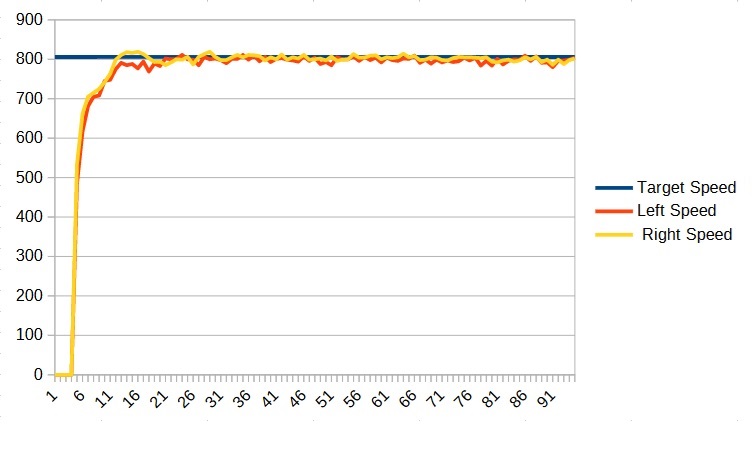
This should result in a graph which looks something like this:
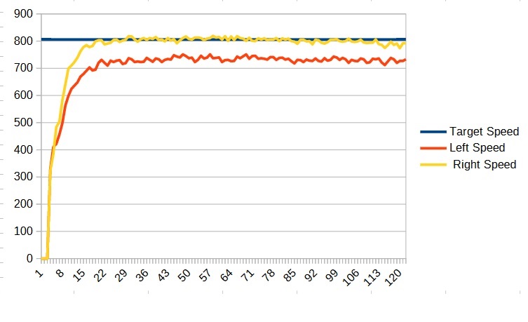
The blue line represents the target speed and the red and yellow lines are the actual speeds of the motors. We can see that some of the motors are close and some need to be adjusted. We can find a new value by taking the ratio of the target speed to the actual speed. For example for the left metal motor the desired speed is 800 but it is running at only 750 which gives us a ratio of 800/750 or about 1.07 so we need to increase the left F term by 1.07. (In the case of the blue motor the values would be 0.98 for the left and 1.05 for the right)
|
1 2 3 4 5 |
private static final double k_Fleft = 1.07/k_maxSpeed; // Use the correct number for your robot private static final double k_Fright = 1.0/k_maxSpeed; // Use the correct number for your robot // private static final double k_Fleft = 0.98 / k_maxSpeed; // Blue Motor // private static final double k_Fright = 1.05 / k_maxSpeed; // Blue Motor |
Remember that these numbers are for this particular robot only. Your robot may behave slightly differently and you should adjust your number accordingly.
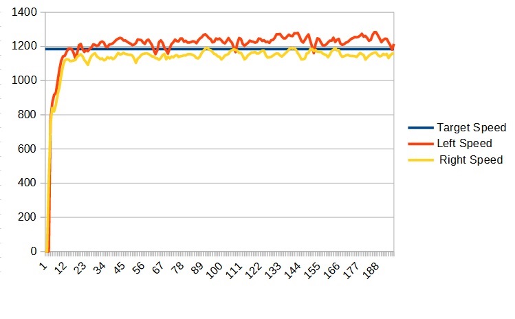
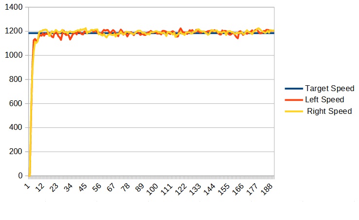
Now run your program again and copy the data to LibreOffice Calc and you should get a graph something like:
Now this is much better and we can see that our robot is already driving much straighter. We can continue to adjust the F values to try and get it closer to the target, but we don’t need it to be perfect. The P and I terms will compensate for it being a little bit off.
Now that we have the F term established we are going to work on the P term. The P stands for proportional. What this means is that power is added or subtracted depending on how far off the actual speed is from the target speed – the further we are from the target speed, the more this term will add/subtract and get it closer. Determining the first guess for the P term is somewhat difficult so we are just going to try something and see how it works. This term is best used in small doses, so let’s try 0.0002 (in this case we won’t need to use different values for the two motors).
To set the P term we add the following to the DriveSubsystem constructor:
|
1 2 |
m_leftMotor.setPTerm(k_P); m_rightMotor.setPTerm(k_P); |
And defining k_P as follows:
|
1 |
private static final double k_P = 0.0002; |
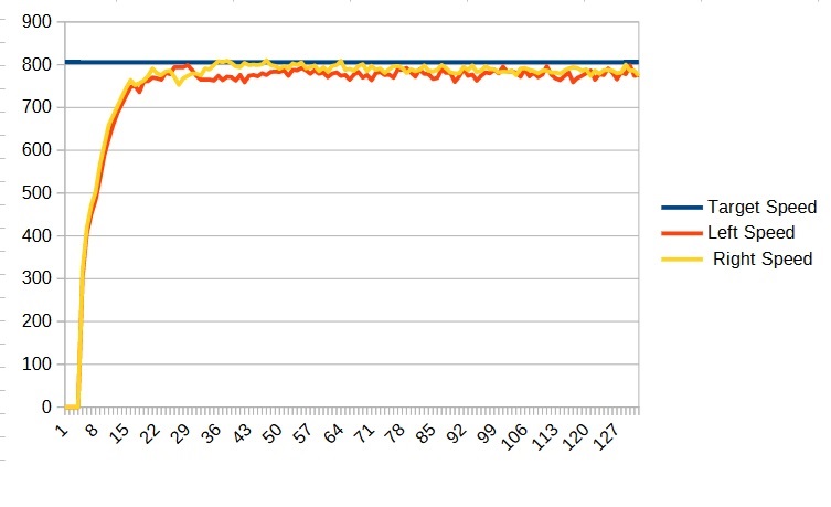
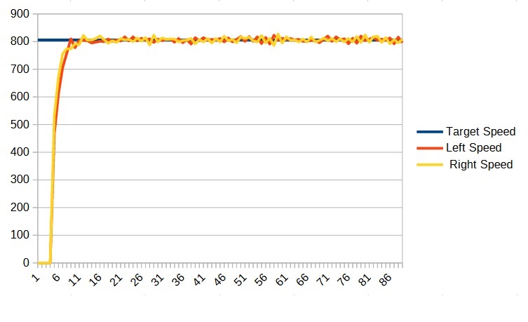
Using this value, we get the following graph:
We can see that this graph already looks better than the previous one that did not have a P term. Now what we want is the largest value of P that does not make the robot unstable. If P is too large, the robot will start to oscillate and we don’t want that. So what we are going to do is keep increasing the value of P until we see it become unstable, and then back off.
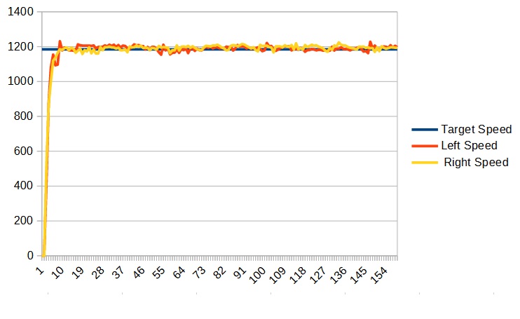
In my case, I kept increasing P until I reached 0.01 (0.005) at which point my graph looked like:
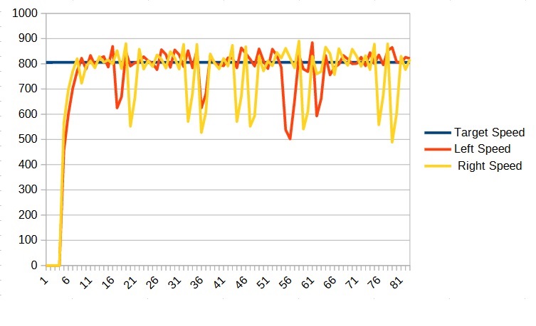
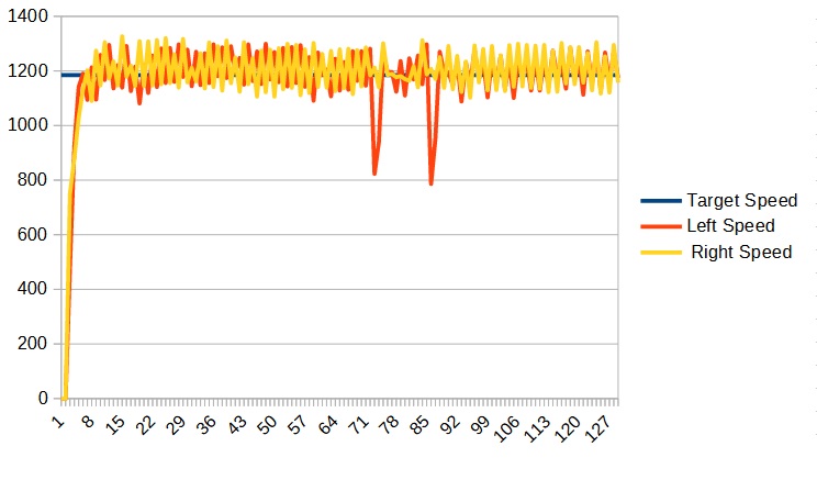
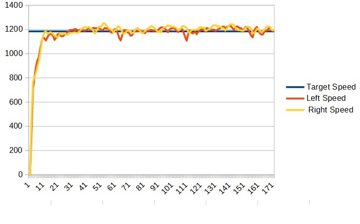
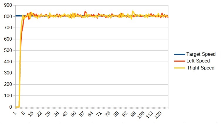
We can see that it has become unstable. So at this point I decreased the P value and settled on a P of 0.002 (0.001) which looked like:
Now adding the P term helps a lot but if the robot were to encounter some additional resistance (such as going up a ramp) it would not be able to completely compensate. For that we need the I term.
The I stands for integral. What the PID controller does is run in a loop. Each time through the loop it computes an error term which is the difference between the set point and the actual speed. The P term then multiplies that error term to make it’s adjustment. However, the PID loop also keeps track of a total error, and each time through the loop its error term is added to the total error. The I term is then multiplied by the total error and that is added to the power equation.
So, lets say, that the speed is too low because the robot is going up a ramp. As long as the speed is too slow, the total error will continue to increase which will cause the power applied to continue to increase until there is enough power to maintain the correct speed.
Once again choosing an initial value for the I term is difficult and we will have to make a guess. Like the P correction factor, its best to start small. Let’s start with 0.001. We set the I term like this:(again, in the DriveSubsystem constructor):
|
1 2 |
m_leftMotor.setITerm(k_I); m_rightMotor.setITerm(k_I); |
Defining k_I as follows:
|
1 |
private static final double k_I = 0.001; |
There is one last thing we need to do before we run our program. Using the I term is great but really only works when our speed is close to the target value. When we first start the robot, it takes some time for the robot to get up to speed and during that time we build up a large total error term. This then causes us to overshoot our target. Eventually it settles down to the correct value but we don’t want the overshoot. The way to prevent this is to only use the I term when the current speed is close to the target speed.
We set this range by using the setIZone() function. We need to set the zone large enough that it encompasses the natural oscillation of the motors. Looking at the graphs we can see the motor speeds aren’t straight lines, but they stay within a narrow range. This range is around 50. Set the I Zone as follows:
|
1 2 |
m_leftMotor.setIZone(k_IZone); m_rightMotor.setIZone(k_IZone); |
Defining k_IZone as:
|
1 |
private static final double k_IZone = 50; |
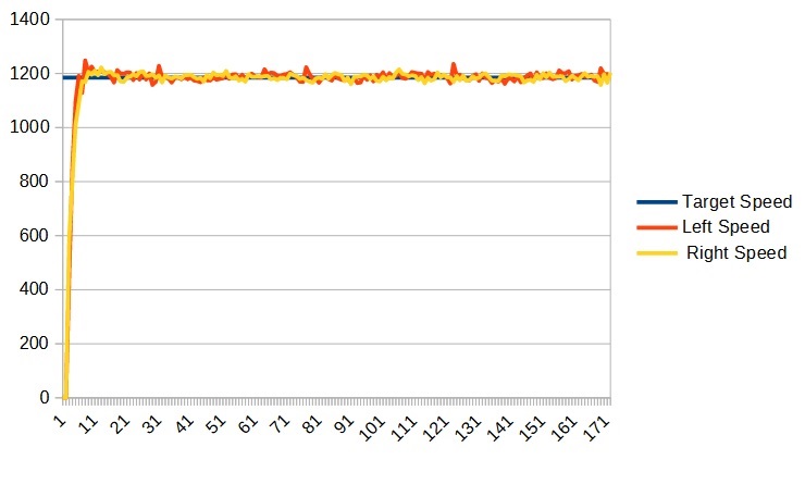
Now we run the program and, as with the P term, we continue to increase the I term until it becomes unstable and then we back off to the last stable value. For me I settled on an I of 0.002 (0.0005) which game me a graph like:
Your DriveSubsystem.java file should now look something like:
|
1 2 3 4 5 6 7 8 9 10 11 12 13 14 15 16 17 18 19 20 21 22 23 24 25 26 27 28 29 30 31 32 33 34 35 36 37 38 39 40 41 42 43 44 45 46 47 48 49 50 51 52 53 54 55 56 57 58 59 60 61 62 63 64 65 66 67 68 69 70 71 72 73 74 75 76 77 78 79 80 81 82 83 84 85 86 87 88 89 90 91 92 93 94 95 96 97 98 99 100 101 102 103 104 105 106 107 108 109 110 111 112 113 114 115 116 117 |
/*----------------------------------------------------------------------------*/ /* Copyright (c) 2018-2019 FIRST. All Rights Reserved. */ /* Open Source Software - may be modified and shared by FRC teams. The code */ /* must be accompanied by the FIRST BSD license file in the root directory of */ /* the project. */ /*----------------------------------------------------------------------------*/ package frc.robot.subsystems; import edu.wpi.first.wpilibj2.command.SubsystemBase; import robotCore.Device; import robotCore.Encoder; import robotCore.Logger; import robotCore.PWMMotor; import robotCore.SmartMotor.SmartMotorMode; public class DriveSubsystem extends SubsystemBase { //Define motor constructor arguments before Constructor calls private static final int k_leftMotorPWMPin = Device.M1_2_PWM; private static final int k_leftMotorDirPin = Device.M1_2_DIR; private static final int k_rightMotorPWMPin = Device.M1_1_PWM; private static final int k_rightMotorDirPin = Device.M1_1_DIR; //Define encoder constructor arguments before Constrctor calls private static final int k_leftEncoderPin1 = Device.Q1_INT; private static final int k_leftEncoderPin2 = Device.Q1_DIR; private static final int k_rightEncoderPin1 = Device.Q2_INT; private static final int k_rightEncoderPin2 = Device.Q2_DIR; //Define motor-specific constants //NOTE: Use the correct numbers for *YOUR* robot! public static final int k_maxSpeed = 1075; private static final double k_leftMinPower = 0.3; private static final double k_rightMinPower = 0.3; //PID values private static final double k_Fleft = 1.07 / k_maxSpeed; private static final double k_Fright = 1.0 / k_maxSpeed; private static final double k_P = 0.005; private static final double k_I = 0.002; private static final double k_IZone = 50; // Define motor variables // and Instantiate and assign PWMMotor objects, left and right private PWMMotor m_leftMotor = new PWMMotor(k_leftMotorPWMPin, k_leftMotorDirPin); private PWMMotor m_rightMotor = new PWMMotor(k_rightMotorPWMPin, k_rightMotorDirPin); //Instantiate and assign Encoder objects, left and right. private Encoder m_leftEncoder = new Encoder(robotCore.Encoder.EncoderType.Quadrature, k_leftEncoderPin1, k_leftEncoderPin2); private Encoder m_rightEncoder = new Encoder(robotCore.Encoder.EncoderType.Quadrature, k_rightEncoderPin1, k_rightEncoderPin2); /** * Creates a new DriveSubsystem. */ public DriveSubsystem() { Logger.log("DriveSubsystem", 3, "DriveSubsystem()"); m_rightEncoder.setInverted(true); m_leftMotor.setFeedbackDevice(m_leftEncoder); m_rightMotor.setFeedbackDevice(m_rightEncoder); m_leftMotor.setMaxSpeed(k_maxSpeed); m_rightMotor.setMaxSpeed(k_maxSpeed); m_leftMotor.setMinPower(k_leftMinPower); m_rightMotor.setMinPower(k_rightMinPower); m_leftMotor.setFTerm(k_Fleft); m_rightMotor.setFTerm(k_Fright); m_leftMotor.setPTerm(k_P); m_rightMotor.setPTerm(k_P); m_leftMotor.setITerm(k_I); m_rightMotor.setITerm(k_I); m_leftMotor.setIZone(k_IZone); m_rightMotor.setIZone(k_IZone); } //Return the left encoder value public Encoder getLeftEncoder() { return (m_leftEncoder); } //Return the right encoder value public Encoder getRightEncoder() { return (m_rightEncoder); } //Sets the power for the motors. //Sets both motors to the same power. // leftPower & rightPower are -1.0 (full rev) to 1.0 (full fwd) public void setPower(double leftPower, double rightPower) { m_leftMotor.setControlMode(SmartMotorMode.Power); m_rightMotor.setControlMode(SmartMotorMode.Power); m_rightMotor.set(rightPower); m_leftMotor.set(leftPower); } //Sets the speed for the motors public void setSpeed(double leftSpeed, double rightSpeed) { m_leftMotor.setControlMode(SmartMotorMode.Speed); m_rightMotor.setControlMode(SmartMotorMode.Speed); m_leftMotor.set(leftSpeed); m_rightMotor.set(rightSpeed); } @Override public void periodic() { // This method will be called once per scheduler run Logger.log("DriveSubsystem", -1, "periodic()"); } } |
Remember that the actual values for the F, I, and P terms for your robot may differ from the ones shown here.
Before we wrap up, let’s see how it behaves at another other speeds. Here are my graphs for 0.75, 0.5, and 0.25:
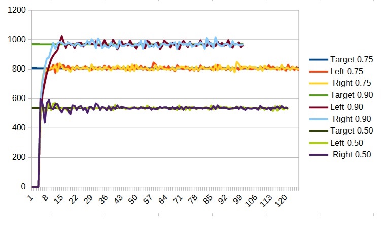
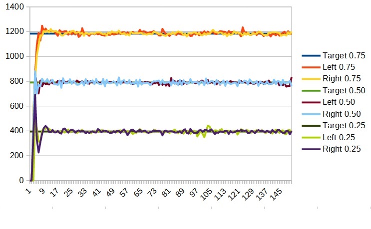
We can see that it looks pretty good. There is a bit of an overshoot at the beginning for the 0.9 and 0.5 speeds but it is not significant so we will not muck with the PID values. The fact is, no single set of PID terms is going to work for all speeds. When tuning your robot you should tune it for the speed that is most important. You should then check other speeds and adjust the PID parameters only if there is a serious problem.
Let’s make one last change before we move on. Change the call to setPower in the ArcadeDrive() function to setSpeed. This will allow us to control the robot by speed even during teleop which can make it easier to control your robot, especially if the two motors run at different speeds for the same power setting. Your ArcadeDriveCommand.java file should now look like:
|
1 2 3 4 5 6 7 8 9 10 11 12 13 14 15 16 17 18 19 20 21 22 23 24 25 26 27 28 29 30 31 32 33 34 35 36 37 38 39 40 41 42 43 44 45 46 47 48 49 50 51 52 53 54 55 56 57 58 59 60 61 62 63 64 65 66 67 68 69 |
/*----------------------------------------------------------------------------*/ /* Copyright (c) 2018-2019 FIRST. All Rights Reserved. */ /* Open Source Software - may be modified and shared by FRC teams. The code */ /* must be accompanied by the FIRST BSD license file in the root directory of */ /* the project. */ /*----------------------------------------------------------------------------*/ package frc.robot.commands; import edu.wpi.first.wpilibj2.command.Command; import edu.wpi.first.wpilibj2.command.button.CommandJoystick; import frc.robot.subsystems.DriveSubsystem; import robotCore.Logger; /** * Command that drives the robot as an Arcade Drive. */ public class ArcadeDriveCommand extends Command { private final DriveSubsystem m_subsystem; private final CommandJoystick m_joystick; /** * Creates a new ArcadeDriveCommand. * * @param subsystem The subsystem used by this command. */ public ArcadeDriveCommand(DriveSubsystem subsystem, CommandJoystick joystick) { Logger.log("ArcadeDriveCommand", 3, "ArcadeDriveCommand()"); m_subsystem = subsystem; m_joystick = joystick; // Use addRequirements() here to declare subsystem dependencies. addRequirements(m_subsystem); } // Called when the command is initially scheduled. @Override public void initialize() { Logger.log("ArcadeDriveCommand", 2, "initialize()"); } // Called every time the scheduler runs while the command is scheduled. @Override public void execute() { Logger.log("ArcadeDriveCommand", -1, "execute()"); double y = m_joystick.getY(); double x = m_joystick.getX(); x = Math.abs(x) * x; y = Math.abs(y) * y; m_subsystem.setSpeed(y + x, y - x); } // Called once the command ends or is interrupted. @Override public void end(boolean interrupted) { Logger.log("ArcadeDriveCommand", 2, String.format("end(%b)", interrupted)); } // Returns true when the command should end. @Override public boolean isFinished() { Logger.log("ArcadeDriveCommand", -1, "isFinished()"); return false; } } |
Optional: Another Way to Clear the Terminal Window
Make sure the TERMINAL terminal window is showing at the bottom of VSCode by (1) clicking the word TERMINAL. Then (2) left-click the three dots on the right (near the “X” in the corner).
This will bring up a window with a Clear Terminal option. Click it to clear the window.
ALTERNATIVELY, if the Clear Terminal icon shows up, click it instead!